6
NETWORK CABLE TESTER OPERATION
Note: Make sure the battery power is sufcient. Insufcient battery power will lead to
dimmed LEDs and potentially incorrect results.
Base-T Test
• Plug one end of the cable to be tested into the transmitting RJ45 jack on the
master unit marked with a ‘ ‘ and the other end of the cable into the remaining
receiving RJ45 jack.
• Slide power switch on. The upper row of LEDs will start to scan in sequence if the
Auto/Manual button is set on “Auto” mode. The LED for pin 1 will light up if the
button is in “Manual” mode.
• Switch from Auto to Manual scanning mode by pressing the Auto/Manual button on
the side of the master-testing unit.
• Once both ends of the cable are plugged in correctly, the second row of LEDs will
illuminate according to the corresponding LEDs in the top row.
• Read the results of the LED display for the pin conguration status of the tested
cable. If you fail to read the results the rst time in Auto mode, you may wait for the
second LED scan, or simply switch to Manual mode for pin by pin testing.
• In Manual mode, pressing the “Test” button will advance testing to the next pin.
RJ11 Modular Cable Test
• Plug one end of the cable to be tested into the transmitting RJ45 jack on the
master unit marked with a ‘ ‘ and the other end of the cable into the remaining
receiving RJ45 jack.
• The method of testing is similar to that for RJ45 except only the middle 4 pins are
used.
Coaxial Cable Test
• Plug the two attached BNC adapter cables into both RJ45 jacks. Then connect the
cable to be tested to each end of the BNC adapter cables.
• For the remaining testing procedures, please refer to 10Base-T Test steps 2 to 5
• Slide the power switch to on.
• As Coaxial cable has only two wires, we suggest you read the result of the LED
scan using Manual mode.
• The centre pin of a BNC cable should be read on LED 2.
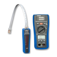
Remote Cable Test
• Plug one end of the cable to be tested to the transmitting RJ45 jack on the master
unit marked with a ‘ ‘.
• Plug the other end into the remote terminator. If the cable to be tested is installed
in a patch panel or wall plate, you may use the included patch cable to solve the
connector gender problem.
• Set the Auto/Manual switch to Auto mode for one-person testing.
• Read the test results from the LED display on the remote terminator.
Note: The LED display on the remote unit will scan in sequence corresponding to the
transmitting end of the master unit.
Caution: Operating the tester in live circuits may damage the tester.
 Loading...