POWER AND CONNECT
Connect the larger 4-pin connector on the ACI Control + Power Y-cable to the Control/Power input
on the ACI unit (G), then connect the smaller 4-pin connector to the CTRL port on the I/O expander.
1
2
Attach a RED or RED-approved I/O expander and power source to the camera.
4
Attach the ACI unit rmly against the side of the
DSMC2 camera using the alignment guides in
the attachment brackets, then tighten the four
screws (C) with the Hex L key.
Connect power to the ACI by attaching the P-Tap connector on the Y-cable to the power source.
3
If using an MDR.ACI unit, attach the motor(s) to the rods/lens, then connect the motor(s) to the
corresponding motor ports (L) using a 4-pin connector. The motors will calibrate after connecting power.
4
NOTE: The camera serial communication setting must be set to RCP (Redlink Command
Protocol) for the unit to operate.
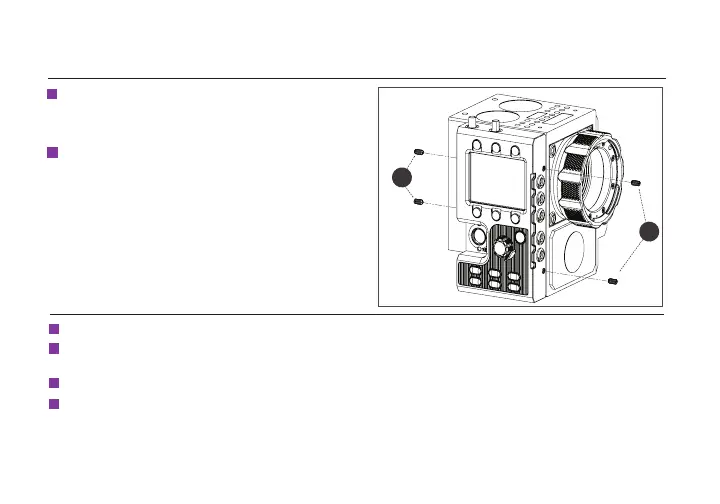
MOUNTING INSTRUCTIONS (CONT.)
C
C
3
Insert the four set screws (C) on the ACI unit
so that they do not interfere with the notched
areas.
3