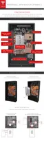
STEP 4 - SET THE ADDRESS SWITCHES
The DIP switch block has three white pins numbered “1”, “2”, and “3” from top to bottom with a
value of ‘1’ to the left and ‘0’ to the right. Use these switches to set the Powerwall address.
Set the switches according to each Powerwall's position, per the table below. Set a single
Powerwall using Powerwall 0 settings.
Note: Always check with the inverter partner for inverter abilities and instructions before
connecting multiple Powerwalls.
Address Switches Powerwall 0 Powerwall 1
Switch 1 Right Left
Switch 2 Right Right
Switch 3 Right Right
These switch settings create the addresses below for each unit.
Protocol
Powerwall 0 Address Powerwall 1 Address
Modbus 24 25
CAN 80 81
Step-by-Step Installation Instructions
Tesla Energy 11

 Loading...