5 First steps
33
• 6 : Halves the currently selected value. Accelerates if the
button remains pressed.
• 7 : Decreases the currently selected value. Accelerates if the
button remains pressed.
8 The trigger signal input socket is used if an external trigger (e.g.
rotational speed sensor) is used to control the flash sequence.
Pos: 23 /TD/Produktb eschreibung/Statusa nzeigen 477 @ 4\mod_124956 3194258_79.doc @ 47253 @ 2
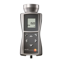
4.2. Status displays
The following status displays may appear in the lowest line in the
display:
• LOBAT: lights up if the rechargeable battery must be
charged again or the battery must be exchanged.
• INT: lights up when the flashing frequency is generated by
the instrument. The units are displayed with FPM as
standard.
• EXT: lights up upon switching to an external trigger signal.
The units are displayed as standard with 1/min (revolutions
per minute).
• RANGE: lights up when the external trigger signal causes a
flashing frequency that is too high.
Pos: 24 /TD/Überschr iften/5. Erste Schr itte @ 0\mod_1173774895039_ 79.doc @ 319 @ 1
5 First steps
Pos: 25 /TD/Überschr iften/5.1 Inbetriebn ahme @ 0\mod_1185342823 812_79.doc @ 1885 @ 2
5.1. Commissioning
Pos: 26 /TD/Erste Sc hritte/testo 477/Batter ien einlegen @ 4\mod_124 9037621082_79.doc @ 46759 @ 3
5.1.1. Inserting batteries/rechargeable batteries
Only operate and store instrument with battery
compartment cover.
If the instrument is not used for a longer period, remove all
batteries/rechargeable batteries from the instrument.
Incompletely charged batteries/rechargeable batteries
reduce the operating time.
1. Loosen screws on the bottom of the instrument.
2 Remove battery compartment cover.
3. Insert batteries (AA)/NiMH rechargeable batteries (AA) (observe
the polarity!)
4. Close the battery compartment cover.
5. Tighten screws.