testo 6621 - Commissioning14
2
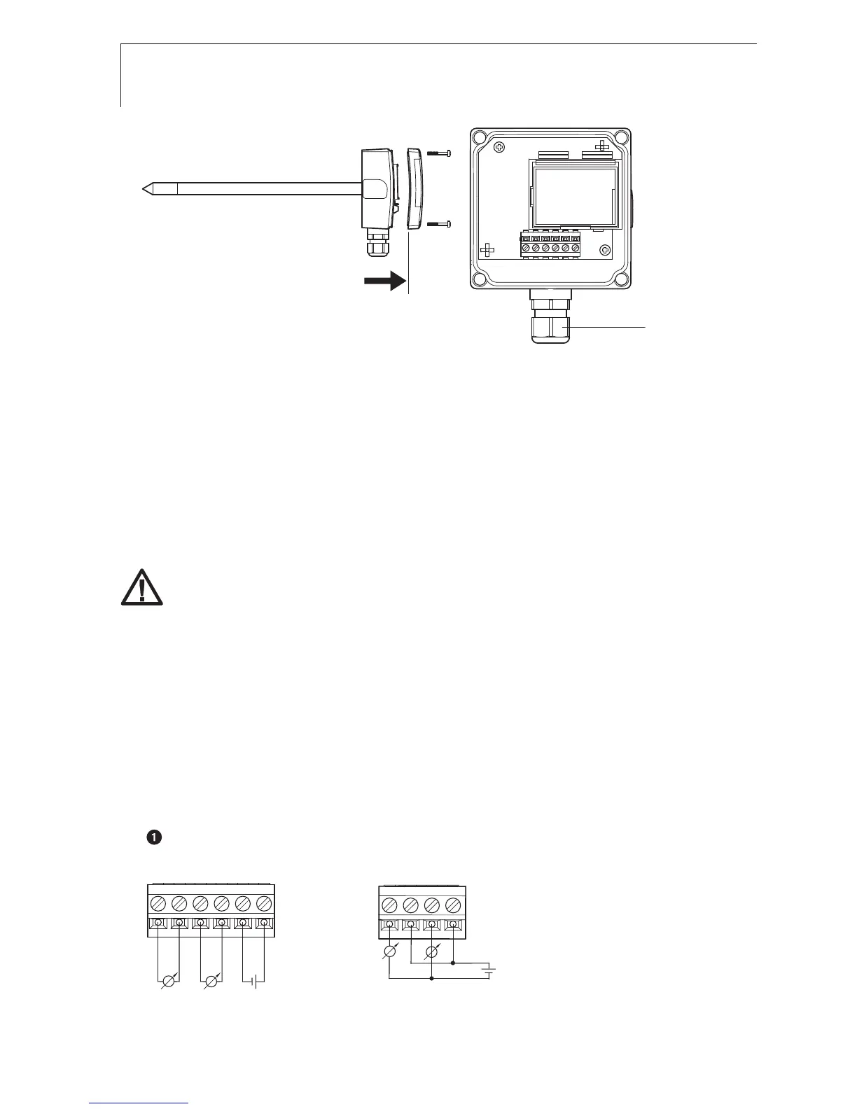
To open the housing: Loosen the 4 screws in the upper part of the
housing (
) and remove the upper part of the housing (
).
3 Guide the cable through the cable coupling (
) into the lower part of the
housing.
4 After wiring (see below): Close the cable coupling to fix the cable (right-
handed thread) and replace upper part of housing.
Wiring the instrument
Make sure when routing the cables that there is space between the
signal lines and interfering external lines.
If electromagnetic interference is likely, use a shielded and/or twisted
cable. The shield must be connected to earth on the side facing away
from the transmitter. Recommendation: 8-wire line with a tightly plaited
shield, wire cross-section of 0.25 - 0.5 mm².
If overvoltages are likely, install overvoltage protection devices.
Wire the instrument according to the application in hand:
2-wire/4-wire technology (2 analog outputs active)
testo 6621
(wall)
View of wiring side (rear of housing)
Voltage output A01 (4-wire,
0 - 1 V/0 - 5 V/0 - 10 V):
U = 20 - 30 VDC/AC
Current output A03
(2-wire, 4...20 mA),
max. load 500 Ω