LoadCharger
EV2300/EV2400
SMB I2C HDQ
USB
bq27220EVM Quick Start Guide
www.ti.com
4
SLUUBF5–April 2016
Submit Documentation Feedback
Copyright © 2016, Texas Instruments Incorporated
bq27220EVM-744 Evaluation Module
2.5.1 Connecting the bq27220 Circuit Module to a Battery Pack
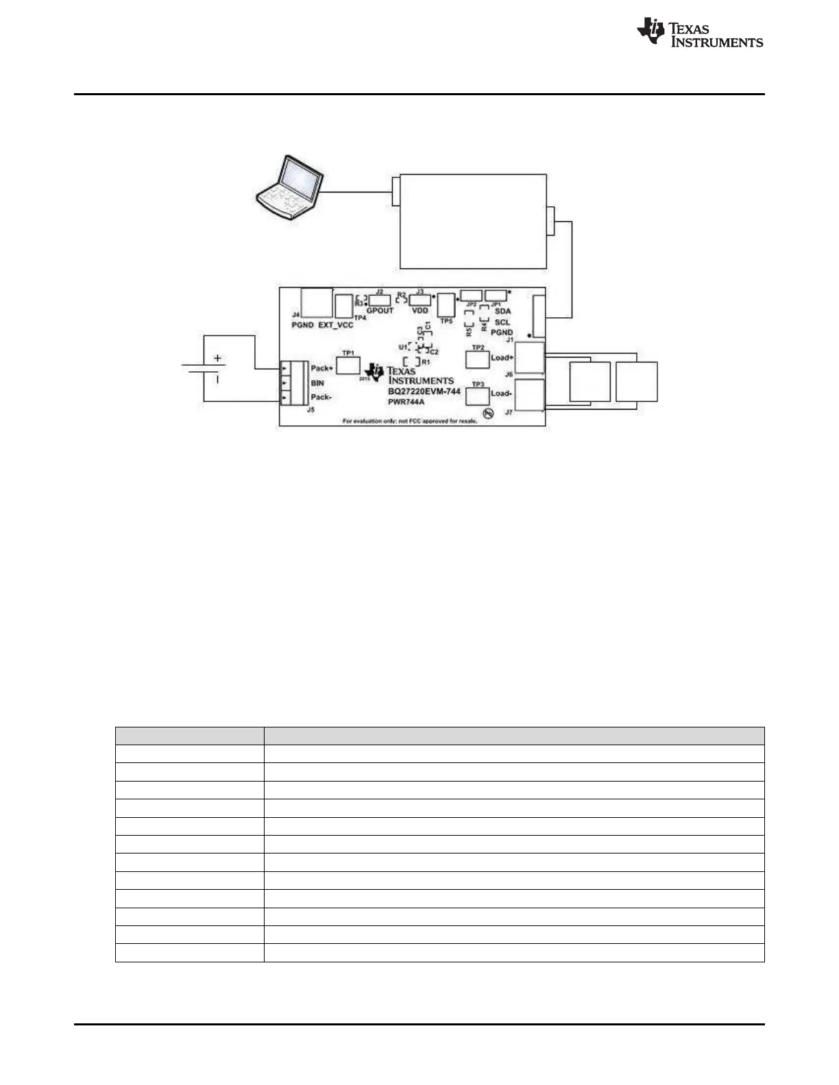
Figure 1 illustrates the device connection to a battery and system load and charger.
Figure 1. bq27220 Circuit Module Connection to Pack and System Load/Charger
2.5.2 Circuit Module Connections
Contacts on the circuit module provide the following connections:
• Direct connection to the battery pack (J6): PACK+/PACK–
• Charger and load connection (J7 and J8): LOAD+ and LOAD–
• I2C communication port (J5): SDA, SCL, and VSS
• Signal outputs (J3): SOC_INT, SDQ and BAT_GD
• External power connection (J1): EXT
2.5.3 Pin Description
Table 3 lists the EVM pins and their descriptions.
Table 3. EVM Pins Descriptions
Pin Name Description
PACK+ Pack positive terminal
PACK– Pack negative terminal
TS Pack thermistor connection
SDA I2C communication data line
SCL I2C communication clock line
BAT_GD Battery Good push-pull indicator output
SOC_INT SOC state interrupts output
SDQ Communication interface to authentication ID IC using SDQ protocol
CE Chip enable
EXT External supply connection
LOAD+ High potential of load or charger connection
LOAD– Low potential of load or charger connection