6.2 PCB Layout
6.2.1 SENS063 (INA228EVM, INA237EVM, INA238EVM)
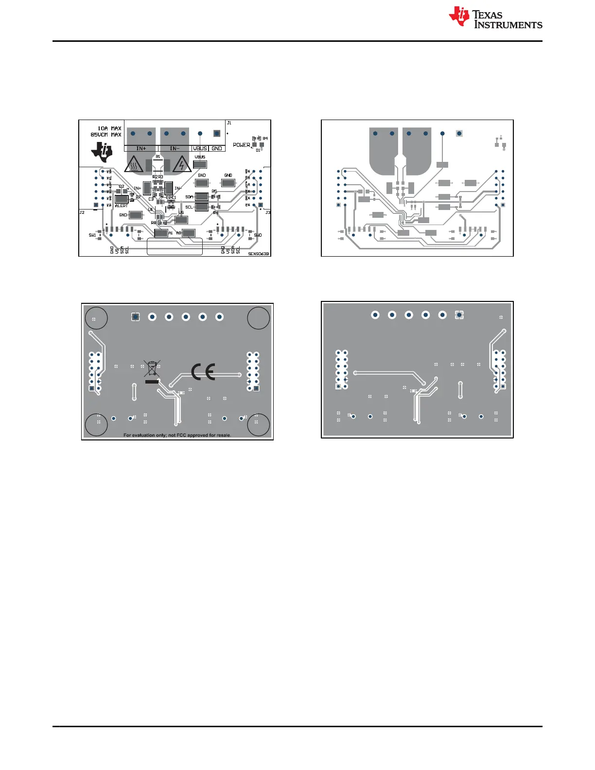
Figure 6-5 through Figure 6-8 illustrate the PCB layers of the EVM.
Figure 6-5. SENS063 Top View Figure 6-6. SENS063 Top Layer
Figure 6-7. SENS063 Bottom View
Figure 6-8. SENS063 Bottom Layer
Schematics, PCB Layout, and Bill of Materials www.ti.com
26 INA228, INA229, INA237, INA238, and INA239 EVM User’s Guide SBOU241C – APRIL 2020 – REVISED JULY 2021
Submit Document Feedback
Copyright © 2021 Texas Instruments Incorporated
 Loading...


