Jacinto™ 7 EVM Quick Start Guide
for DRA821 Processor
8
Texas Instruments
Appendix A: Installing the Automotive Gateway/
Ethernet Switch/Industrial Expansion card onto the
common processor board
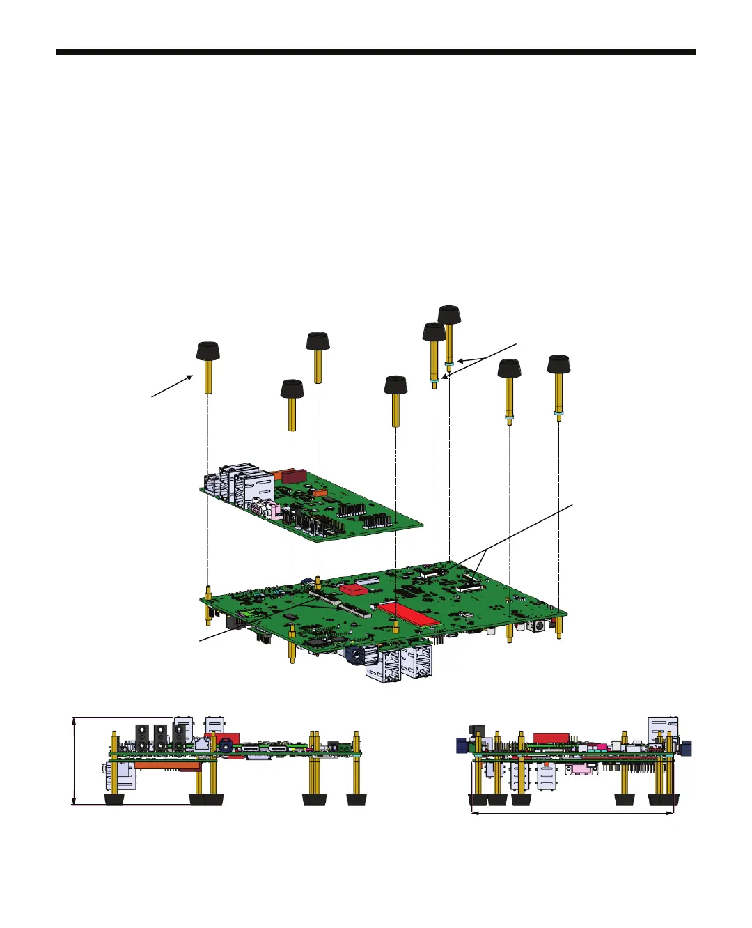
1. Remove the stand-offs (8x) from the EVM. Mate the expansion card to the common processor board
expansion connectors (see bottom left).
2. Press rmly on the edges to ensure the connectors mate (may have to apply signicant pressure).
3. If a CSI expansion board is not connected to the CSI expansion connectors on the common
processor board, add a 2mm thick washer to each of the four stand-offs (see bottom right) on the
common processor board. Washers are included in the kit.
4. Re-install the eight stand-offs.
Connectors
Connectors
Front view
Side view
190.5 ±0.5
82.2 ±0.5