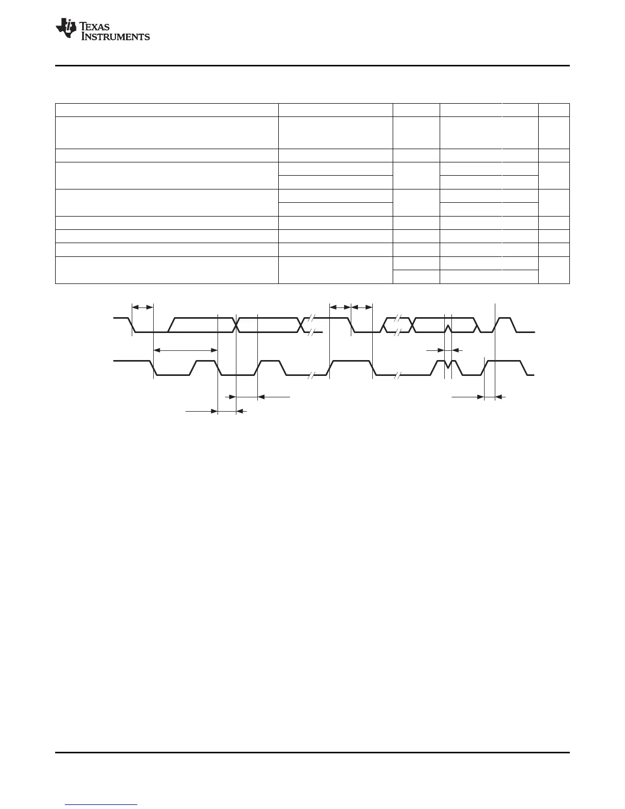
SDA
SCL
1/f
SCL
t
HD,DAT
t
SU,DAT
t
HD,STA
t
SU,STA
t
HD,STA
t
SU,STO
t
SP
MSP430F23x
MSP430F24x(1)
MSP430F2410
www.ti.com
SLAS547I –JUNE 2007–REVISED DECEMBER 2012
USCI (I
2
C Mode)
over recommended ranges of supply voltage and operating free-air temperature (unless otherwise noted) (see Figure 31)
PARAMETER TEST CONDITIONS V
CC
MIN TYP MAX UNIT
Internal: SMCLK, ACLK
f
USCI
USCI input clock frequency External: UCLK f
SYSTEM
MHz
Duty cycle = 50% ± 10%
f
SCL
SCL clock frequency 2.2 V, 3 V 0 400 kHz
f
SCL
≤ 100 kHz 4
t
HD,STA
Hold time (repeated) START 2.2 V, 3 V µs
f
SCL
> 100 kHz 0.6
f
SCL
≤ 100 kHz 4.7
t
SU,STA
Setup time for a repeated START 2.2 V, 3 V µs
f
SCL
> 100 kHz 0.6
t
HD,DAT
Data hold time 2.2 V, 3 V 0 ns
t
SU,DAT
Data setup time 2.2 V, 3 V 250 ns
t
SU,STO
Setup time for STOP 2.2 V, 3 V 4 µs
2.2 V 50 150 600
t
SP
Pulse width of spikes suppressed by input filter ns
3 V 50 100 600
Figure 31. I
2
C Mode Timing
Copyright © 2007–2012, Texas Instruments Incorporated Submit Documentation Feedback 57
 Loading...


