MSP430F23x
MSP430F24x(1)
MSP430F2410
SLAS547I –JUNE 2007–REVISED DECEMBER 2012
www.ti.com
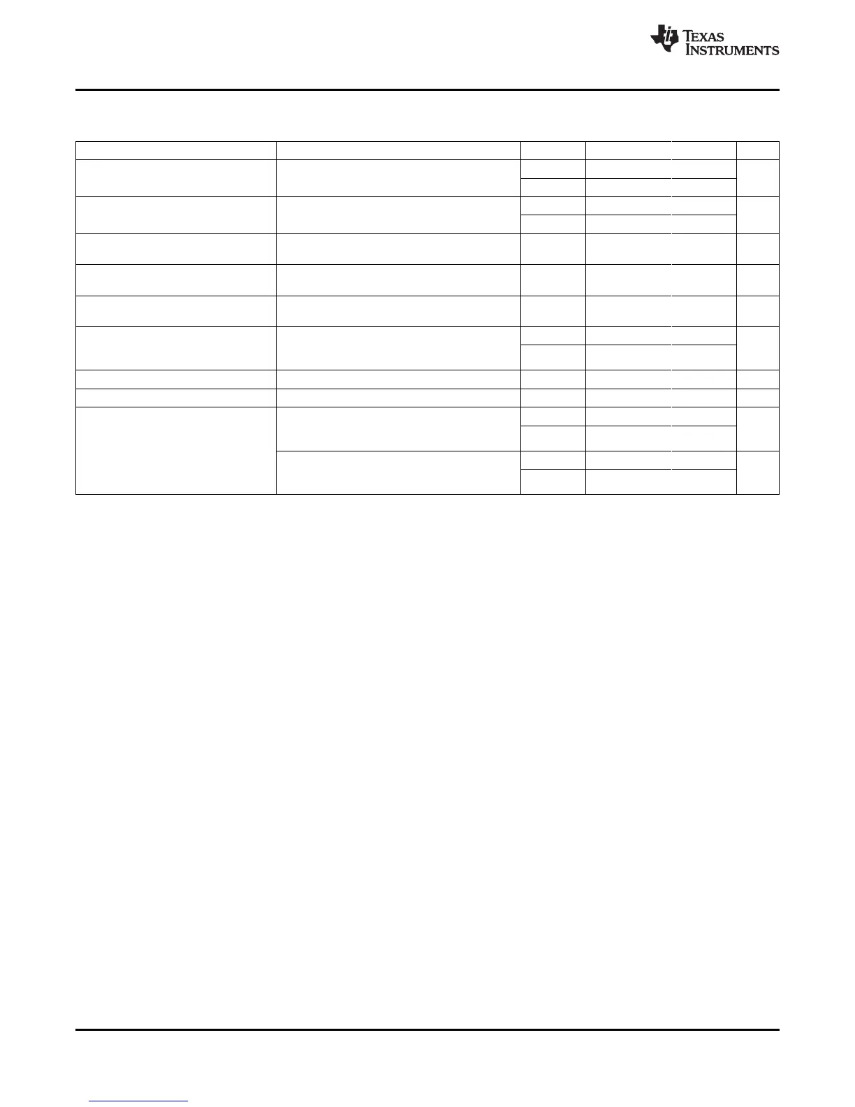
Comparator_A+
(1)
over recommended operating free-air temperature range (unless otherwise noted)
PARAMETER TEST CONDITIONS V
CC
MIN TYP MAX UNIT
2.2 V 25 40
I
(DD)
CAON = 1, CARSEL = 0, CAREF = 0 µA
3 V 45 60
2.2 V 30 50
CAON = 1, CARSEL = 0, CAREF = 1/2/3,
I
(Refladder/RefDiode)
µA
No load at P2.3/CA0/TA1 and P2.4/CA1/TA2
3 V 45 71
Common-mode input
V
IC
CAON = 1 2.2 V, 3 V 0 V
CC
- 1 V
voltage range
Voltage at 0.25 V
CC
PCA0 = 1, CARSEL = 1, CAREF = 1,
V
(Ref025)
2.2 V, 3 V 0.23 0.24 0.25
node / V
CC
No load at P2.3/CA0/TA1 and P2.4/CA1/TA2
Voltage at 0.5 V
CC
node / PCA0 = 1, CARSEL = 1, CAREF = 2,
V
(Ref050)
2.2 V, 3 V 0.47 0.48 0.5
V
CC
No load at P2.3/CA0/TA1 and P2.4/CA1/TA2
PCA0 = 1, CARSEL = 1, CAREF = 3, 2.2 V 390 480 540
See Figure 36 and
V
(RefVT)
No load at P2.3/CA0/TA1 and P2.4/CA1/TA2, mV
Figure 37
3 V 400 490 550
T
A
= 85°C
V
(offset)
Offset voltage
(2)
2.2 V, 3 V -30 30 mV
V
hys
Input hysteresis CAON = 1 2.2 V, 3 V 0 0.7 1.4 mV
T
A
= 25°C, Overdrive 10 mV, 2.2 V 80 165 300
Without filter: CAF = 0
(3)
ns
Response time 3 V 70 120 240
(see Figure 32 and Figure 33)
t
(response)
(low-to-high and high-to-
T
A
= 25°C, Overdrive 10 mV, 2.2 V 1.4 1.9 2.8
low)
Without filter: CAF = 1
(3)
µs
3 V 0.9 1.5 2.2
(see Figure 32 and Figure 33)
(1) The leakage current for the Comparator_A+ terminals is identical to I
lkg(Px.y)
specification.
(2) The input offset voltage can be cancelled by using the CAEX bit to invert the Comparator_A+ inputs on successive measurements. The
two successive measurements are then summed together.
(3) The response time is measured at P2.2/CAOUT/TA0/CA4 with an input voltage step, with Comparator_A+ already enabled (CAON = 1).
If CAON is set at the same time, a settling time of up to 300 ns is added to the response time.
58 Submit Documentation Feedback Copyright © 2007–2012, Texas Instruments Incorporated
 Loading...


