MSP430F23x
MSP430F24x(1)
MSP430F2410
SLAS547I –JUNE 2007–REVISED DECEMBER 2012
www.ti.com
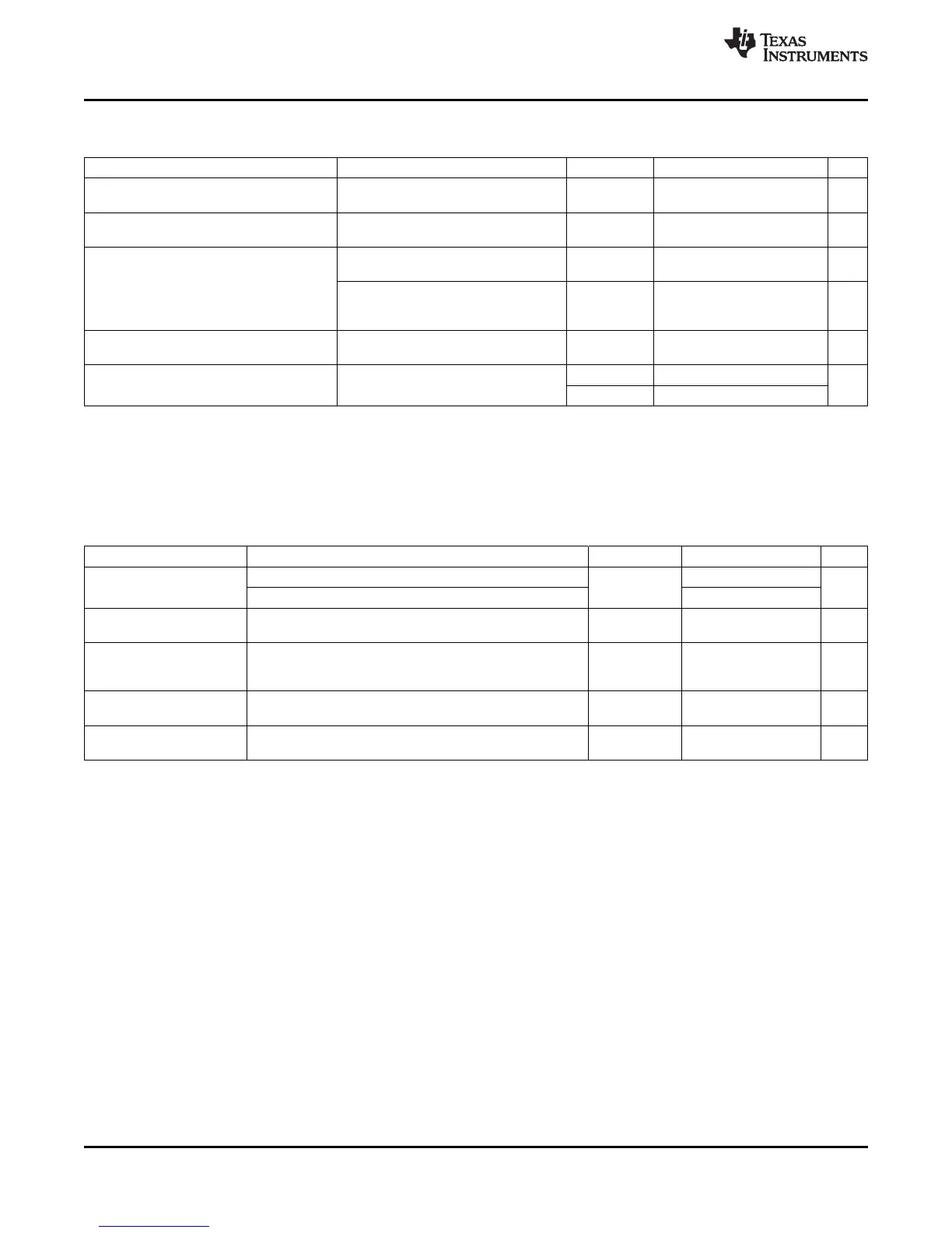
12-Bit ADC, Timing Parameters
over recommended operating free-air temperature range (unless otherwise noted)
PARAMETER TEST CONDITIONS V
CC
MIN NOM MAX UNIT
For specified performance of ADC12
f
ADC12CLK
2.2 V, 3 V 0.45 5 6.3 MHz
linearity parameters
ADC12DIV = 0,
f
ADC12OSC
Internal ADC12 oscillator 2.2 V, 3 V 3.7 5 6.3 MHz
f
ADC12CLK
= f
ADC12OSC
C
VREF+
≥ 5 µF, Internal oscillator,
2.2 V, 3 V 2.06 3.51 µs
f
ADC12OSC
= 3.7 MHz to 6.3 MHz
t
CONVERT
Conversion time
External f
ADC12CLK
from ACLK, MCLK, 13 ×
or SMCLK, ADC12DIV × µs
ADC12SSEL ≉ 0 1/f
ADC12CLK
Turn-on settling time of the
t
ADC12ON
See
(2)
100 ns
ADC
(1)
3 V 1220
R
S
= 400 Ω,R
I
= 1000 Ω, C
I
= 30 pF,
t
Sample
Sampling time
(1)
ns
τ = [R
S
+R
I
] × C
I
(3)
2.2 V 1400
(1) Limits verified by design
(2) The condition is that the error in a conversion started after t
ADC12ON
is less than ±0.5 LSB. The reference and input signal are already
settled.
(3) Approximately ten Tau (τ) are needed to get an error of less than ±0.5 LSB:
t
Sample
= ln(2
n+1
) × (R
S
+ R
I
) × C
I
+ 800 ns, where n = ADC resolution = 12, R
S
= external source resistance
12-Bit ADC, Linearity Parameters
over recommended operating free-air temperature range (unless otherwise noted)
PARAMETER TEST CONDITIONS V
CC
MIN NOM MAX UNIT
1.4 V ≤ (V
eREF+
– V
REF–
/V
eREF–
) min ≤ 1.6 V ±2
Integral linearity
E
I
2.2 V, 3 V LSB
error
1.6 V < (V
eREF+
– V
REF–
/V
eREF–
) min ≤ V
AVCC
±1.7
Differential linearity (V
eREF+
– V
REF–
/V
eREF–
) min ≤ (V
eREF+
– V
REF–
/V
eREF–
),
E
D
2.2 V, 3 V ±1 LSB
error C
VREF+
= 10 µF (tantalum) and 100 nF (ceramic)
(V
eREF+
– V
REF–
/V
eREF–
) min ≤ (V
eREF+
– V
REF–
/V
eREF–
),
E
O
Offset error Internal impedance of source RS < 100 Ω, 2.2 V, 3 V ±2 ±4 LSB
C
VREF+
= 10 µF (tantalum) and 100 nF (ceramic)
(V
eREF+
– V
REF–
/V
eREF–
)min ≤ (V
eREF+
– V
REF–
/V
eREF–
),
E
G
Gain error 2.2 V, 3 V ±1.1 ±2 LSB
C
VREF+
= 10 µF (tantalum) and 100 nF (ceramic)
Total unadjusted (V
eREF+
-– V
REF–
/V
eREF–
)min ≤ (V
eREF+
–V
REF–
/V
eREF–
),
E
T
2.2 V, 3 V ±2 ±5 LSB
error C
VREF+
= 10 µF (tantalum) and 100 nF (ceramic)
64 Submit Documentation Feedback Copyright © 2007–2012, Texas Instruments Incorporated

 Loading...


