Step 4:
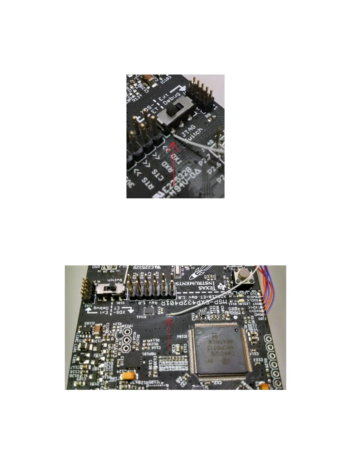
Attach a wire for the “TDI” signal by soldering a wire into pin 6 of the debug select switch (S101) as
shown in the figure below. Ensure that the switch remains in the “XDS-ET” position.
Figure 5: Wire Soldered to "TDI" Signal on S101
Step 5:
Attach a wire for the “SWO” signal by soldering a wire to pin 12 of IC111. Since the traces are small on
that component, it is easiest to attach the wire directly to the trace.
Figure 6: Wire Soldered to "SWO" Signal from Pin 12 on IC111

 Loading...


