EasyManua.ls Logo

Texas Instruments TMS570LS0714 - User Manual

Texas Instruments TMS570LS0714
162 pages
Print Icon
To Next Page IconTo Next Page
Loading...
Product
Folder
Sample &
Buy
Technical
Documents
Tools &
Software
Support &
Community
An IMPORTANT NOTICE at the end of this data sheet addresses availability, warranty, changes, use in safety-critical applications,
intellectual property matters and other important disclaimers. PRODUCTION DATA.
TMS570LS0714
SPNS226E –JUNE 2013–REVISED NOVEMBER 2016
TMS570LS0714 16- and 32-Bit RISC Flash Microcontroller
1 Device Overview
1
1.1 Features
1
• High-Performance Automotive-Grade
Microcontroller (MCU) for Safety-Critical
Applications
– Dual CPUs Running in Lockstep
– ECC on Flash and RAM Interfaces
– Built-In Self-Test (BIST) for CPU and On-chip
RAMs
– Error Signaling Module With Error Pin
– Voltage and Clock Monitoring
• ARM
®
Cortex
®
-R4F 32-Bit RISC CPU
– 1.66 DMIPS/MHz With 8-Stage Pipeline
– FPU With Single and Double Precision
– 12-Region Memory Protection Unit (MPU)
– Open Architecture With Third-Party Support
• Operating Conditions
– Up to 160-MHz System Clock
– Core Supply Voltage (VCC): 1.14 to 1.32 V
– I/O Supply Voltage (VCCIO): 3.0 to 3.6 V
• Integrated Memory
– 768KB of Flash With ECC
– 128KB of RAM With ECC
– 64KB of Flash for Emulated EEPROM With
ECC
• Common Platform Architecture
– Consistent Memory Map Across Family
– Real-Time Interrupt Timer (RTI) OS Timer
– 128-Channel Vectored Interrupt Module (VIM)
– 2-Channel Cyclic Redundancy Checker (CRC)
• Direct Memory Access (DMA) Controller
– 16 Channels and 32 Peripheral Requests
– Parity for Control Packet RAM
– DMA Accesses Protected by Dedicated MPU
• Frequency-Modulated Phase-Locked Loop
(FMPLL) With Built-In Slip Detector
• IEEE 1149.1 JTAG, Boundary Scan and ARM
CoreSight™ Components
• Advanced JTAG Security Module (AJSM)
• Up to 64 General-Purpose I/O (GIO) Pins
– Up to 16 GIO Pins With Interrupt Generation
Capability
• Enhanced Timing Peripherals
– 7 Enhanced Pulse Width Modulator (ePWM)
Modules
– 6 Enhanced Capture (eCAP) Modules
– 2 Enhanced Quadrature Encoder Pulse (eQEP)
Modules
• Two Next Generation High-End Timer (N2HET)
Modules
– N2HET1: 32 Programmable Channels
– N2HET2: 18 Programmable Channels
– 160-Word Instruction RAM With Parity
Protection Each
– Each N2HET Includes Hardware Angle
Generator
– Dedicated High-End Timer Transfer Unit (HTU)
for Each N2HET
• Two 12-Bit Multibuffered ADC Modules
– ADC1: 24 Channels
– ADC2: 16 Channels
– 16 Shared Channels
– 64 Result Buffers With Parity Protection Each
• Multiple Communication Interfaces
– Up to Three CAN Controllers (DCANs)
– 64 Mailboxes With Parity Protection Each
– Compliant to CAN Protocol Version 2.0A and
2.0B
– Inter-Integrated Circuit (I
2
C)
– 3 Multibuffered Serial Peripheral Interfaces
(MibSPIs)
– 128 Words With Parity Protection Each
– 8 Transfer Groups
– One Standard Serial Peripheral Interface (SPI)
Module
– Two UART (SCI) Interfaces, One With Local
Interconnect Network (LIN 2.1) Interface
Support
• Packages
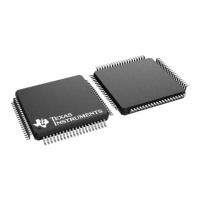
– 144-Pin Quad Flatpack (PGE) [Green]
– 100-Pin Quad Flatpack (PZ) [Green]

Table of Contents

Question and Answer IconNeed help?

Do you have a question about the Texas Instruments TMS570LS0714 and is the answer not in the manual?

Summary

Device Overview

Features

Lists high-level features of the microcontroller, including CPU, memory, and peripherals.

Applications

Describes typical applications like EPS, Braking Systems, Automotive, Aerospace.

Description

Provides a detailed description of the device's architecture and capabilities.

Functional Block Diagram

Illustrates the device's internal structure and interconnects between modules.

Terminal Configuration and Functions

Pin Diagrams

Shows physical pin assignments for the PGE (144-pin) and PZ (100-pin) packages.

Signal Descriptions

Describes the function of each signal pin, including type and internal pullup/pulldown.

Pin Multiplexing

Explains how pins can be multiplexed for different functions, controlled by registers.

Buffer Type

Details output buffer drive strengths and selectable modes like low-EMI.

Specifications

Absolute Maximum Ratings

Defines voltage, current, and temperature limits beyond which damage may occur.

Recommended Operating Conditions

Specifies voltage, temperature, and other conditions for reliable device operation.

Timing and Switching Characteristics

Details timing specifications for clock domains, critical for system design.

System Information and Electrical Specifications

ARM Cortex-R4 F CPU Information

Summarizes features of the ARM Cortex-R4F CPU, including architecture and core implementation.

Clocks

Describes available clock sources, domains, and their configurations for system operation.

Device Memory Map

Outlines the memory map, including flash, RAM, and peripheral register addresses.

Error Signaling Module

Explains the ESM's role in managing error conditions and their severity levels.

Peripheral Information and Electrical Specifications

Enhanced PWM Modules (ePWM)

Details the ePWM modules, their interconnections, synchronization, and trip zones.

12-Bit Multibuffered Analog-to-Digital Converter (MibADC)

Describes the MibADC features, event triggers, and electrical characteristics.

General-Purpose Input;Output

Covers the GPIO module's features, configuration for input/output, and interrupt handling.

Controller Area Network (DCAN)

Highlights DCAN features, protocol support, and electrical specifications.

Device and Documentation Support

Getting Started and Next Steps

Guides users on how to begin development with the device, including tools and kits.

Tools and Software

Lists available hardware kits, evaluation modules, IDEs, compilers, and software tools.

Documentation Support

Provides information on how to get documentation updates and lists related documents.

Trademarks

Lists trademarks associated with the product and Texas Instruments.

Texas Instruments TMS570LS0714 Specifications

General IconGeneral
CoreARM Cortex-R4F
Clock Speed80 MHz
RAM64 KB
Operating Temperature-40°C to 125°C
Operating Voltage3.0 V to 3.6 V
Watchdog TimerYes
Communication InterfacesCAN, SPI, UART
PackageLQFP
Safety FeaturesECC
ADC12-bit ADC

Related product manuals