Flash (768KB)
RAM (128KB)
0x00000000
CRC
Peripherals - Frame 1
SYSTEM Modules
0xFFFFFFFF
RAM - ECC
RESERVED
RESERVED
RESERVED
Flash (768KB) (Mirrored Image)
RESERVED
RESERVED
Peripherals - Frame 2
0xFFF80000
Flash Module Bus2 Interface
RESERVED
0x000BFFFF
0x08000000
0x0801FFFF
0xFE000000
0xFF000000
0xF07FFFFF
0x08400000
0x0841FFFF
0xF0000000
0x200BFFFF
0xFC000000
0xFCFFFFFF
0x20000000
(Flash ECC, OTP and
EEPROM Emulation accesses)
61
TMS570LS0714
www.ti.com
SPNS226E –JUNE 2013–REVISED NOVEMBER 2016
Submit Documentation Feedback
Product Folder Links: TMS570LS0714
System Information and Electrical SpecificationsCopyright © 2013–2016, Texas Instruments Incorporated
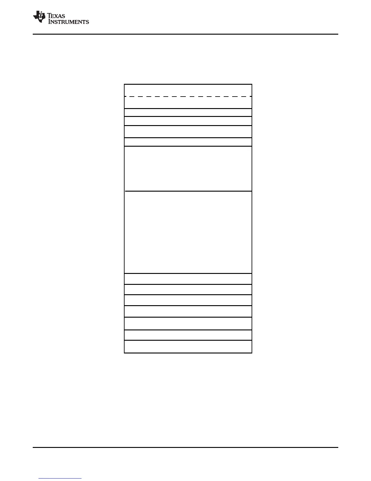
6.9 Device Memory Map
6.9.1 Memory Map Diagram
Figure 6-9 shows the device memory map.
Figure 6-9. Memory Map
The Flash memory is mirrored to support ECC logic testing. The base address of the mirrored Flash
image is 0x2000 0000.
 Loading...


