80
TMS570LS0714
SPNS226E –JUNE 2013–REVISED NOVEMBER 2016
www.ti.com
Submit Documentation Feedback
Product Folder Links: TMS570LS0714
System Information and Electrical Specifications Copyright © 2013–2016, Texas Instruments Incorporated
6.17 Error Signaling Module
The Error Signaling Module (ESM) manages the various error conditions on the TMS570 microcontroller.
The error condition is handled based on a fixed severity level assigned to it. Any severe error condition
can be configured to drive a low level on a dedicated device terminal called nERROR. The nERROR can
be used as an indicator to an external monitor circuit to put the system into a safe state.
6.17.1 ESM Features
The features of the ESM are:
• 128 interrupt/error channels are supported, divided into three groups
– 64 channels with maskable interrupt and configurable error pin behavior
– 32 error channels with nonmaskable interrupt and predefined error pin behavior
– 32 channels with predefined error pin behavior only
• Error pin to signal severe device failure
• Configurable time base for error signal
• Error forcing capability
6.17.2 ESM Channel Assignments
The ESM integrates all the device error conditions and groups them in the order of severity. Group1 is
used for errors of the lowest severity while Group3 is used for errors of the highest severity. The device
response to each error is determined by the severity group it is connected to. Table 6-31 lists the channel
assignment for each group.
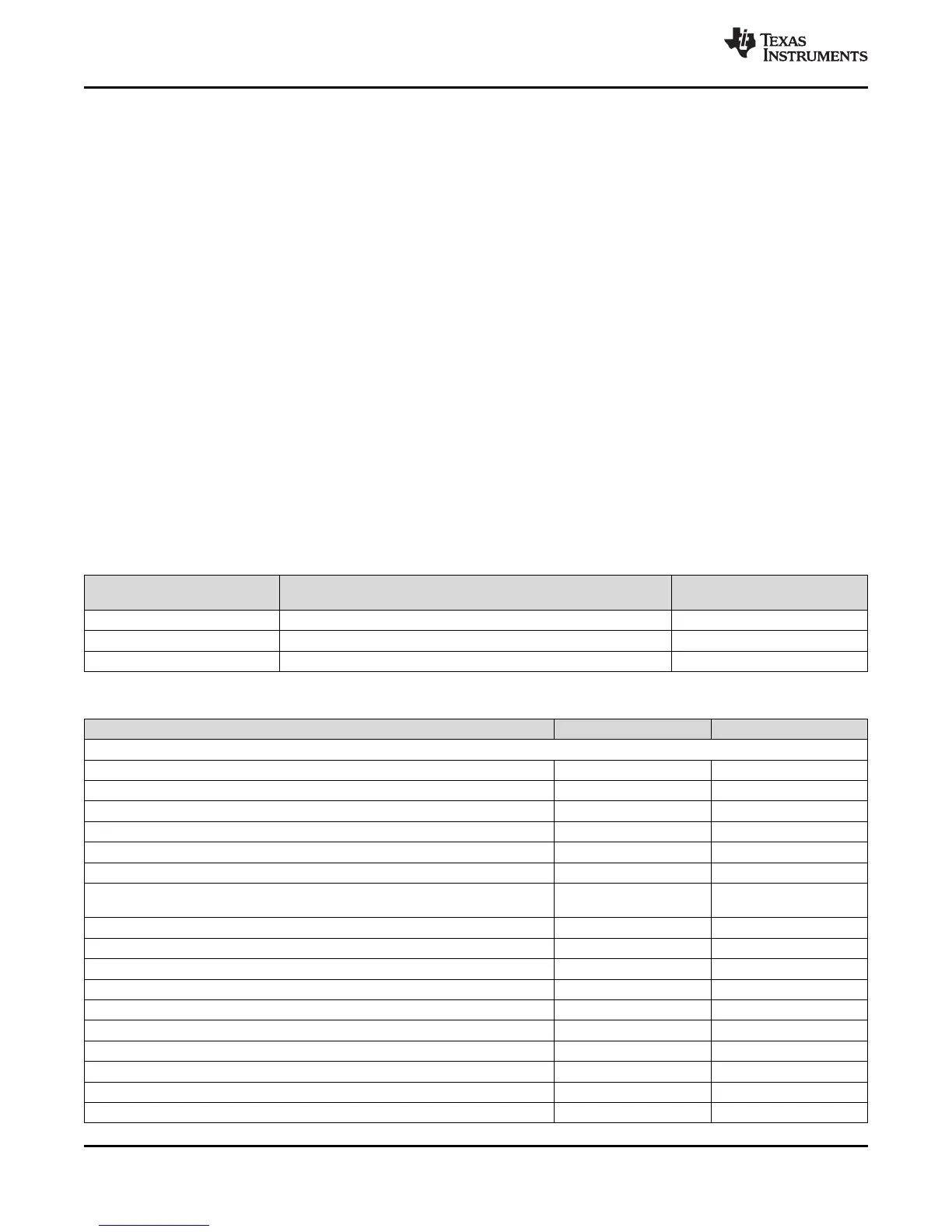
Table 6-30. ESM Groups
ERROR GROUP INTERRUPT CHARACTERISTICS
INFLUENCE ON ERROR
TERMINAL
Group1 Maskable, low or high priority Configurable
Group2 Nonmaskable, high priority Fixed
Group3 No interrupt generated Fixed
Table 6-31. ESM Channel Assignments
ERROR CONDITION GROUP CHANNELS
Group1
Reserved Group1 0
MibADC2 - RAM parity error Group1 1
DMA - MPU configuration violation Group1 2
DMA - control packet RAM parity error Group1 3
Reserved Group1 4
DMA - error on DMA read access, imprecise error Group1 5
FMC - correctable ECC error: bus1 and bus2 interfaces
(does not include accesses to Bank 7)
Group1 6
N2HET1 - RAM parity error Group1 7
HET TU1/HET TU2 - dual-control packet RAM parity error Group1 8
HET TU1/HET TU2 - MPU configuration violation Group1 9
PLL1 - Slip Group1 10
Clock Monitor - oscillator fail Group1 11
Reserved Group1 12
DMA - error on DMA write access, imprecise error Group1 13
Reserved Group1 14
VIM RAM - parity error Group1 15
Reserved Group1 16