36
TMS570LS0714
SPNS226E –JUNE 2013–REVISED NOVEMBER 2016
www.ti.com
Submit Documentation Feedback
Product Folder Links: TMS570LS0714
Specifications Copyright © 2013–2016, Texas Instruments Incorporated
(1) Stresses beyond those listed under Absolute Maximum Ratings may cause permanent damage to the device. These are stress ratings
only, and functional operation of the device at these or any other conditions beyond those indicated under Recommended Operating
Conditions is not implied. Exposure to absolute-maximum-rated conditions for extended periods may affect device reliability.
(2) Maximum-rated conditions for extended periods may affect device reliability. All voltage values are with respect to their associated
grounds.
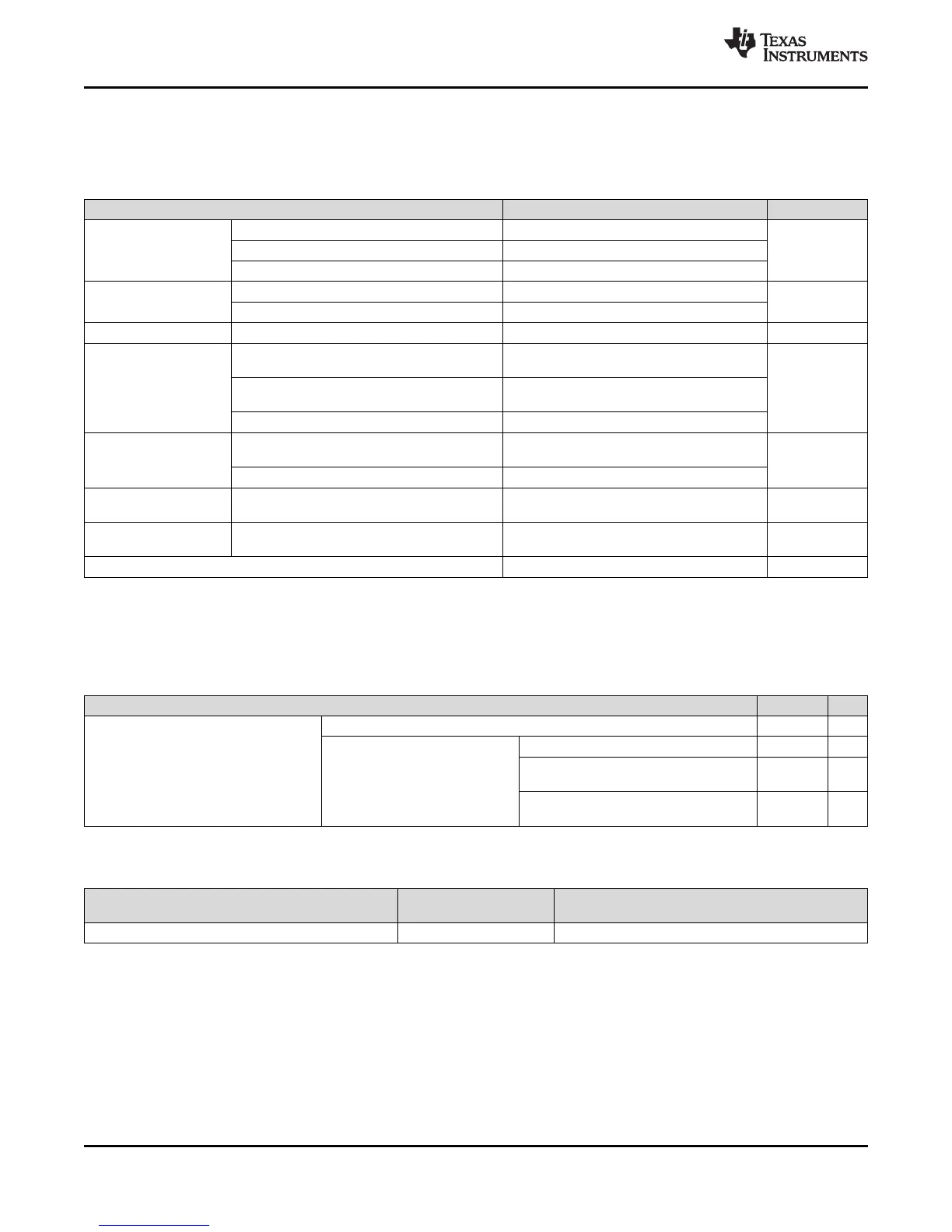
5 Specifications
5.1 Absolute Maximum Ratings
(1)
Over Operating Free-Air Temperature Range
MIN MAX UNIT
Supply voltage range:
V
CC
(2)
–0.3 1.43
VV
CCIO
, V
CCP
(2)
–0.3 4.6
V
CCAD
(2)
–0.3 6.25
Input voltage
All input pins, with exception of ADC pins –0.3 4.6
V
ADC input pins –0.3 6.25
Output voltage All output pins –0.3 4.6 V
Input clamp current
I
IK
(V
I
< 0 or V
I
> V
CCIO
)
All pins, except AD1IN[23:0] or AD2IN[15:0]
–20 20
mAI
IK
(V
I
< 0 or V
I
> V
CCAD
)
AD1IN[23:0] or AD2IN[15:0]
–10 10
Total –40 40
Output clamp current
I
OK
(V
O
< 0 or V
O
> V
CCIO
)
All pins, except AWM1_EXT_x
–20 20
mA
Total –40 40
Operating free-air
temperature (T
A
)
–40 125 °C
Operating junction
temperature (T
J
)
–40 150 °C
Storage temperature (T
stg
) –65 150 °C
(1) AEC Q100-002 indicates HBM stressing is done in accordance with the ANSI/ESDA/JEDEC JS‑001 specification.
5.2 ESD Ratings
VALUE UNIT
V
(ESD)
Electrostatic discharge (ESD)
performance:
Human Body Model (HBM), per AEC Q100-002
(1)
±2 kV
Charged Device Model (CDM),
per AEC Q100-011
All pins ±500 V
100-pin PZ corner pins (1, 25, 26, 50,
51, 75, 76, 100)
±750 V
144-pin PGE corner pins (1, 36, 37, 72,
73, 108, 109, 144)
±750 V
(1) This information is provided solely for your convenience and does not extend or modify the warranty provided under TI's standard terms
and conditions for TI semiconductor products.
(2) To avoid significant degradation, the device power-on hours (POH) must be limited to those specified in this table. To convert to
equivalent POH for a specific temperature profile, see the Calculating Equivalent Power-on-Hours for Hercules Safety MCUs Application
Report (SPNA207).
5.3 Power-On Hours (POH)
(1)(2)
NOMINAL CVDD VOLTAGE (V)
JUNCTION
TEMPERATURE (Tj)
LIFETIME POH
1.2 105ºC 100K