TRST
TMS
TCK
TDI
TDO
RTCK
ICEPICK_C
Boundary Scan
BSR/BSDL
Boundary Scan
Interface
Secondary Tap 0
DAP
Debug APB
Debug
ROM1
APB slave
Cortex
R4F
APB Mux
AHB-AP
POM
To
SCR1
through A2A
From
PCR Bridge
Test Tap 0
eFuse Farm
Secondary Tap 2
AJSM
Test Tap 1
PSCON
88
TMS570LS0714
SPNS226E –JUNE 2013–REVISED NOVEMBER 2016
www.ti.com
Submit Documentation Feedback
Product Folder Links: TMS570LS0714
System Information and Electrical Specifications Copyright © 2013–2016, Texas Instruments Incorporated
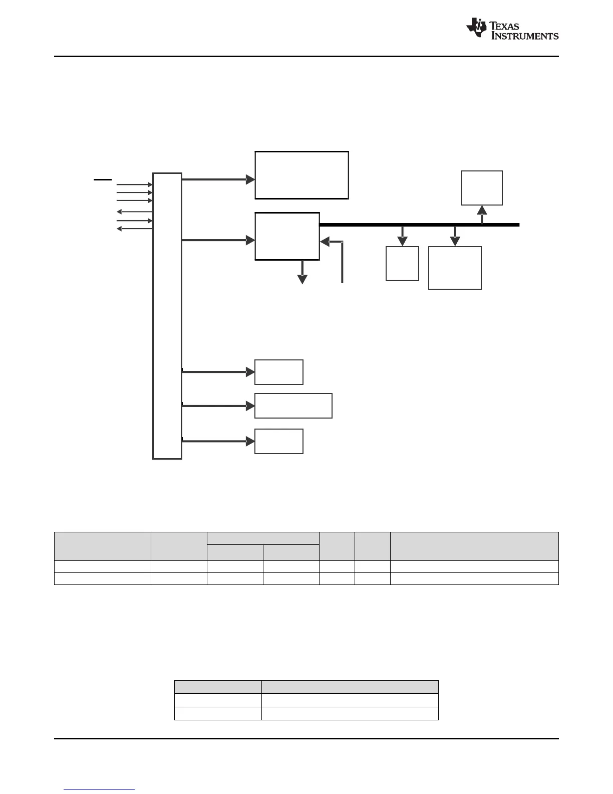
6.20 Debug Subsystem
6.20.1 Block Diagram
The device contains an ICEPICK module (version C) to allow JTAG access to the scan chains (see
Figure 6-14).
Figure 6-14. Debug Subsystem Block Diagram
6.20.2 Debug Components Memory Map
Table 6-33. Debug Components Memory Map
MODULE
NAME
FRAME CHIP
SELECT
FRAME ADDRESS RANGE
FRAME
SIZE
ACTUAL
SIZE
RESPONSE FOR ACCESS TO
UNIMPLEMENTED LOCATIONS
IN FRAME
START END
CoreSight Debug ROM CSCS0 0xFFA0_0000 0xFFA0_0FFF 4KB 4KB Reads return zeros, writes have no effect
Cortex-R4F Debug CSCS1 0xFFA0_1000 0xFFA0_1FFF 4KB 4KB Reads return zeros, writes have no effect
6.20.3 JTAG Identification Code
The JTAG ID code for this device is the same as the device ICEPick Identification Code. For the JTAG ID
Code per silicon revision, see Table 6-34.
Table 6-34. JTAG ID Code
SILICON REVISION ID
Rev 0 0x0BB0302F
Rev A 0x1BB0302F
 Loading...


