www.ti.com
Component Locations
4.2 Component Locations
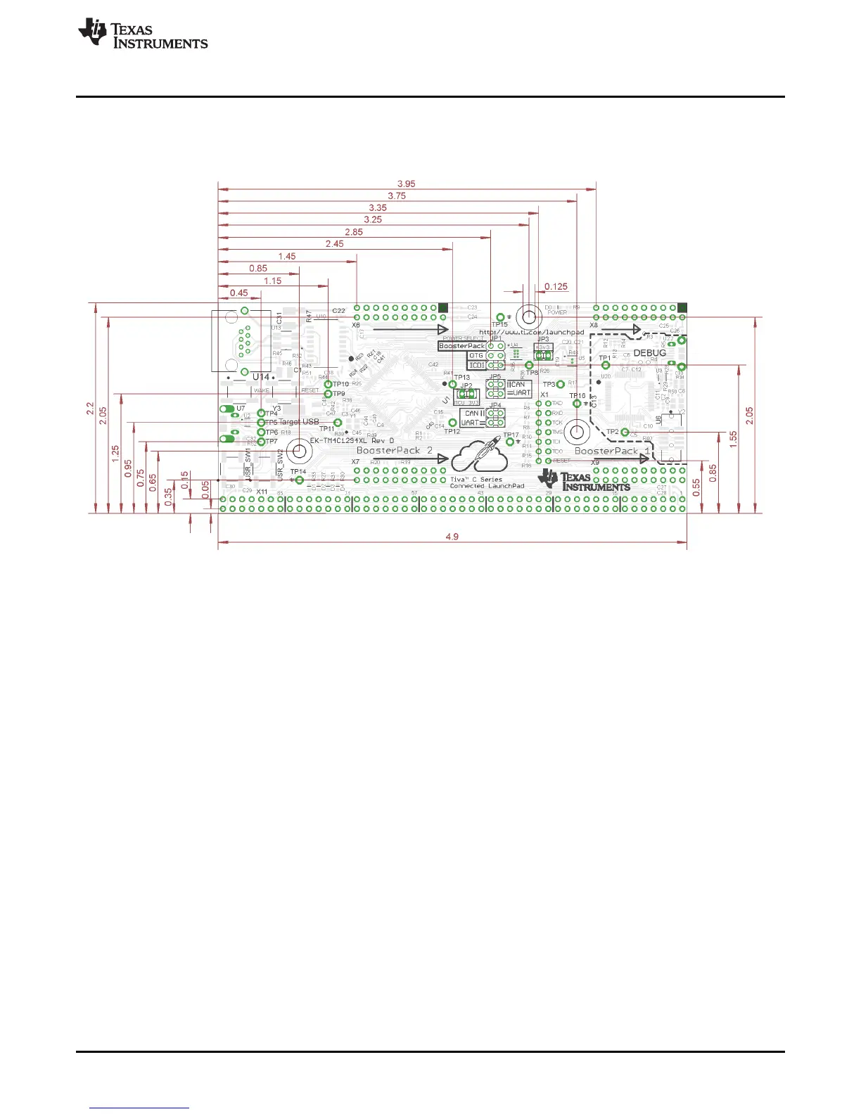
Figure 4-1 is a dimensioned drawing of the Connected LaunchPad. This figure shows the location of
selected features of the board as well as the component locations.
Figure 4-1. Connected LaunchPad Dimensions and Component Locations
23
SPMU365A–March 2014–Revised March 2014 References, PCB Layout, and Bill of Materials
Submit Documentation Feedback
Copyright © 2014, Texas Instruments Incorporated
 Loading...


