49.9
49.9
49.4
49.9
330
GND
330
GND
0.1uF0.1uF
GNDGND
0.1uF0.1uF
75
75
GNDGND
75
75
GND
4700pF
1M
1000pF
R21
R22
R23
R24
D4
R30
D3
R31
C16C17
C18C22
P$1
P$1
P$2
P$2
P$3
P$3
P$6
P$6
P$7
P$7
P$8
P$8
P$9
P$9
P$10
P$10
P$11
P$11
P$14
P$14
P$15
P$15
P$16
P$16
P$1
1
P$2
2
P$3
3
P$4
4
P$5
5
P$6
6
P$7
7
P$8
8
R32
R43
CHASSIS
9
CHASSIS
10
RX+
3
RX-
6
TERM1A
4
TERM1B
5
TERM2A
7
TERM2B
8
TX+
1
TX-
2
R45
R46
C31
R47
C1
EN0RXI_N/5.3B
EN0RXI_P/5.3B
EN0TXO_N/5.3B
EN0TXO_P/5.3B
PF4/3.2C PF0/3.2C
MCU_3V3/5.2A
A
B
C
D
E
A
B
C
D
E
1 2 3 4 5 6
U10
U13
U14
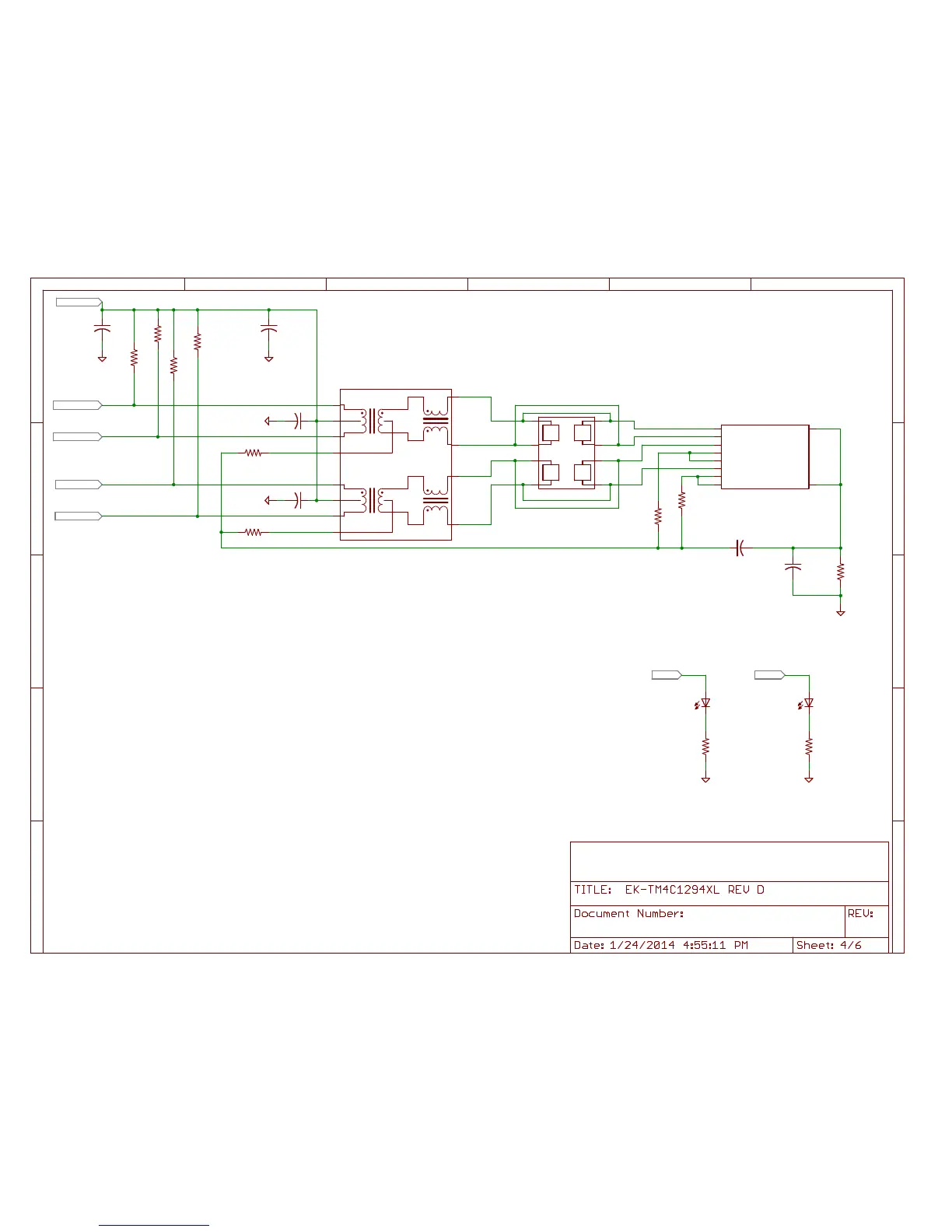
For Ethernet example Applications:
LED4 is default configured as Ethernet Link OK
LED3 is default configured as Ethernet TX/RX activity
User may re-configure these pins / LED's for any
application usage.
Place pull up resistors and C16-C17 near TM4C MCU.
Place C18 and C22 near pin 2 and pin 7 of U$10
U10 May be populated with either HX1188FNL or HX1198FNL.
HX1198FNL preferred for best Ethernet performance.
 Loading...


