Premier LCD & LCDL
LCDLLCDL
LCDL Installation Manual Overview
INS180 5
Tamper Switch
This is the cover tamper switch and provides tamper protection for the keypad.
Output
This output is a low current (100mA ‘-ve’ applied) and can be used to drive auxiliary
devices such as LED’s, sounders or relays etc.
Network Terminals
These terminals must be connected to the corresponding terminals on the control
panel or previous device (see page 8 for wiring details). The ‘+’ and ‘–’ terminals
provide power for the keypad whilst the ‘T’ transmits data and ‘R’ receives data.
!
"
When connecting devices to a keypad that require 12V power i.e. PIR’s etc,
the power must be connected to the ‘+’ and ‘-’ of the network terminals.
Address Switch
This switch sets the address of each keypad (see page 10 for details).
!
"
Never set two keypads on the same network to the same address.
Piezo Sounder
The sounder provides audible indication of the system status i.e. alarm tones,
entry/exit tones, service tones, warning tones and key presses etc.
Zones 1 & 2
These terminals provide the connections for the 2 zones. Each zone can be wired
as Double Pole or End Of Line (2k2 EOL & 4k7 contact).
Speaker Output (Premier LCDL Only)
These terminals can be used for connecting up to one 16Ω or two 8Ω loudspeakers
(see page 12 for wiring details).
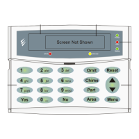
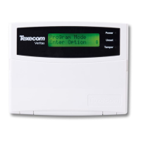
Premier LCD & LCDL Display
The 32-character display is used to show the status of the system and to view
system data.
‘Info.’ LED
The ‘Info.’ LED can be programmed to mimic the keypad output or show the armed
status of an area. For details on programming the ‘Info.’ LED please refer to the
Premier 888/8168 Installation Manual.
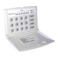
Normal & Function Keys
These keys are used for operating and programming the system.