10
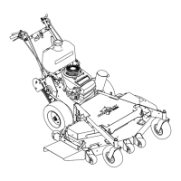
HYDRO
MIDSIZE
8. Remove lag screw (L) from engine deck support.
Leave support bolted to power unit. Open both
dump valves two turns (see page 14) and remove
power unit from pallet. Line power unit up with
cutterdeck. Cutterdeck bracket fits to the outside
of the power unit. Remove cutterdeck belt cover.
9. Loop deck belt over engine pulley (two belts are
provided with cutterdeck–use the shorter one).
NOTE FOR 61" CUTTERDECK HOOKUP:
When a 61" deck is mounted to power unit, the engine
pulley must be first replaced with the one shipped with
the deck. Put the new pulley on with the shoulder to
the same side as the original. Torque the crankshaft
bolt to 50 ft-lbs.
6. Blade control rod (C): Connect to bell crank on left
side of engine deck. Adjust so the blade control
lever snaps over center and locks in the “off”
position.
7. Attach speed control (A) and traction levers (B).
See adjustment section.
10. Bolt cutterdeck and power unit together with six 3/
8-16X1 bolts, twelve washers and six nylock nuts.
Remove rear support from power unit. Remove
assembled unit from cutterdeck pallet.
11. Install the clutch rod into swivel (S) on the idler
arm, under the front LH edge of the engine deck.
Use the shortest rod supplied with the deck.
ASSEMBLY INSTRUCTIONS