www.SteamPoweredRadio.Com
Chapter 5 - Theory of Operation
S
.1
Introduction
This section describes the principles
of
operation
of
the EAS 930A Multi-Module Receiver. It is
intended to enable a technical person with an
RF
background to understand the design
of
the
EAS 930A
at
the block diagram level.
5.2 System Block Diagram Description
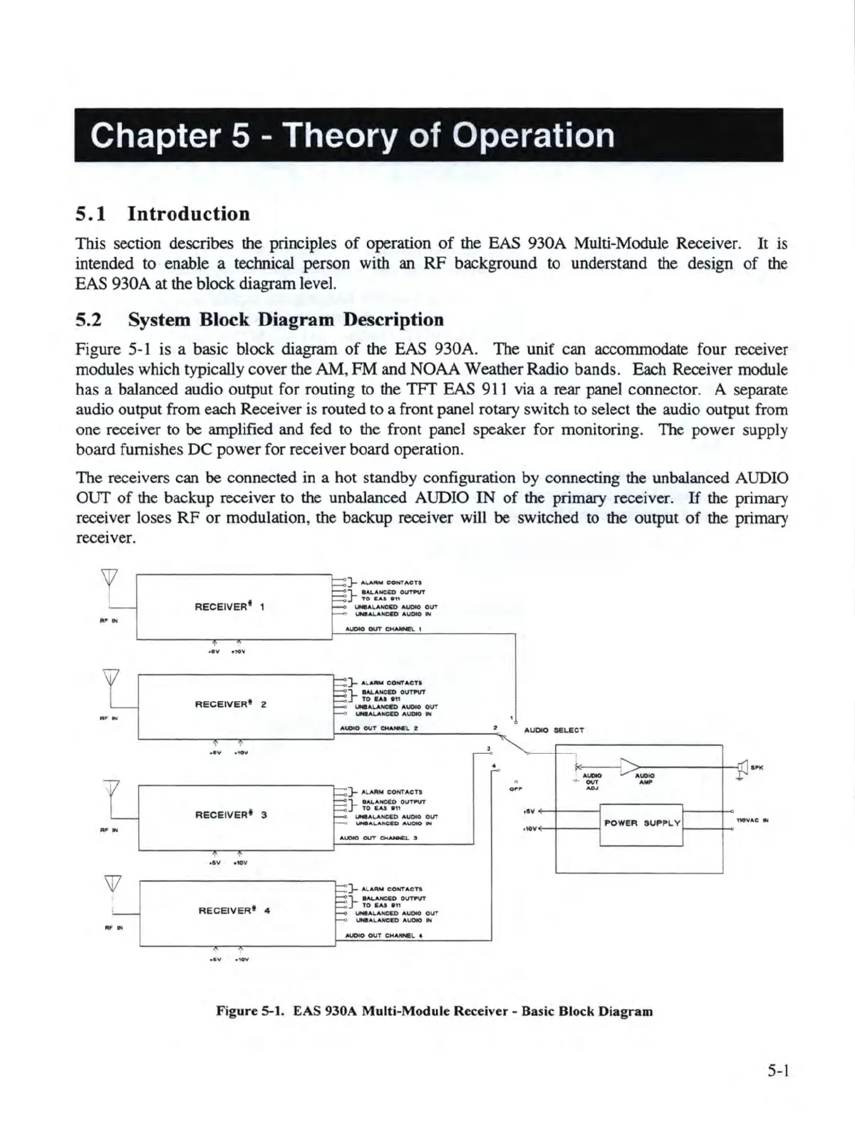
Figure 5-1 is a basic block diagram
of
the EAS 930A. The unif can accommodate four receiver
modules which typically cover the
AM
,
FM
and NOAA Weather Radio bands. Each Receiver module
has a balanced audio output for routing to the
TFf
EAS 911 via a rear panel connector. A separate
audio output from each Receiver is routed to a front panel rotary switch to select the audio output from
one receiver to
be
amplified and fed to the front panel speaker for monitoring. The power supply
board furnishes
DC
power for receiver board operation.
The receivers can
be
connected in a hot standby configuration by connecting the unbalanced AUDIO
OUT
of
the backup receiver to the unbalanced AUDIO
IN
of
the primary receiver.
If
the primary
receiver loses
RF
or
modulation, the backup receiver will
be
switched
to
the output
of
the primary
receiver.
""
..
....
..
"'
.,
w
RECE
IV
ER'
1
RECEIVER
1
2
RECE
I
VER
1
3
I
4V
•tDV
RE
C
EIV
E
R•
4
}-
"""""
CONTACn
}~nounvr
UNa
AJ..AHCCD
.t.U0IO
OVT
UNI
ALANC&D AUDIO
IJr,,I
A
~OUT~1
~
AU,,..
C.
OHTA
CTa
} ~
:-
=-:
1,°"'"""
IJll9AI.ANCCD AUON)
OUT
-..aAJ..ANCCD AIJC»O.,.
)-
A
v.N,I
COHT
A
CTa
}
■
M,.
ANC.lOOt.lff'UT
10
CA.t
en
I.NIA
~
AUDIO
OUT
IMII ...
L.AHCC'O
A
UOIO
N
)-
A
LAIW
COH'TAC·
T·
} :
:-=-:,,01.m"UT
t.Na
A4.AHCCD A
UDIO
OUT
\oN8
A
lAHe&D
AUDIO Ill
AUDIO OUT ~ L 4
A
UO
tO
SE.L6CT
>-----+
-iJ .
....
.
,ov+-+----i
POWER
SU
PP
LY
1--
---ih>
•
10
v••
"'
F
igur
e S-1. EAS 930A Multi-Module Receiver - Basic Block Diagram
5-1