Do you have a question about the The Fire Beam firebeam and is the answer not in the manual?
Explains suitable distances for the standard fire beam and extension kits.
Discusses placement based on roof type, height, and obstruction avoidance.
Instructions for attaching the head unit's backing plate and connecting the head.
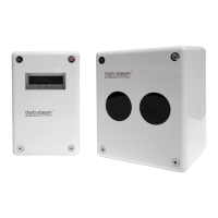
Guidance on mounting the controller at eye level with easy access.
Diagram and details for wiring the system, including cable color functions.
Initial stage of alignment used without the reflector to set beam direction.
Adjusting beam position using X/Y keys to achieve optimal signal.
The system automatically aligns the beam onto the reflector.
Tests the system's response to a simulated fire condition using a filter.
Verifies the beam is correctly reflected by covering the reflector.
Explains screen status (NORMAL, FIRE, FAULT, ERROR) and basic menu controls.
Configuration of alarm reset modes, thresholds, and timing parameters.
Covers dirt compensation, event logging, and beam control features.
Accessing system information like IR power, amplifier gain, and software versions.
Comprehensive details on electrical, environmental, mechanical, and optical parameters.
| Supply Voltage | 10.2 to 40 VDC |
|---|---|
| Supply Current | 3mA |
| Temperature | -10°C to +55°C |
| Humidity | 10 to 95% RH Non-condensing |
| Protection Index | IP65 |
| Optical Wavelength | 870nm |
| Maximum Angular Alignment | ±15° |
| Maximum Angular Misalignment | Beam Head ±0.75° Reflector ±2° |
| Protection Range FIREBEAM | 5 to 40 metres |
| Protection Range 40KIT80 | 40 to 80 metres |
| Protection Range 80KIT100 | 80 to 100 metres |
| Alarm Sensitivity Levels | 25%(1.25dB) to 50%(3dB) |
| Time to Alarm Condition | 2 to 30 seconds |
| Alarm Relay Change Over (CO) Contact Rating | 2A @ 30 VDC |
| Fault Sensitivity Level | 90% |
| Time to Fault Condition | 2 to 60 seconds |
| Fault Relay Change Over (CO) Contact Rating | 2A @ 30 VDC |
| Beam Head Dimensions | 180mmH x 155mmW x137mmD |
|---|---|
| Beam Head Weight | 1.1Kg |
| Controller Dimensions | 185mmH x 120mmW x 62mmD |
| Controller Weight | 0.55Kg |
| 40KIT80 Mid-Range Reflector Dimensions | 293mmH x293mmW x 5mmD |
| 40KIT80 Mid-Range Reflector Weight | 0.8Kg |
| 80KIT100 Long Range Reflector Dimensions | 394mmH x 394mmW x 5mmD |
| 80KIT100 Long Range Reflector Weight | 1.8Kg |
| ADAPTER Dimensions | 270mmH x 250mmW x 5mmD |
| ADAPTER Weight | 0.6Kg |