11
Figure F-5
Figure F-6
Figure F-7a
Figure F-7b
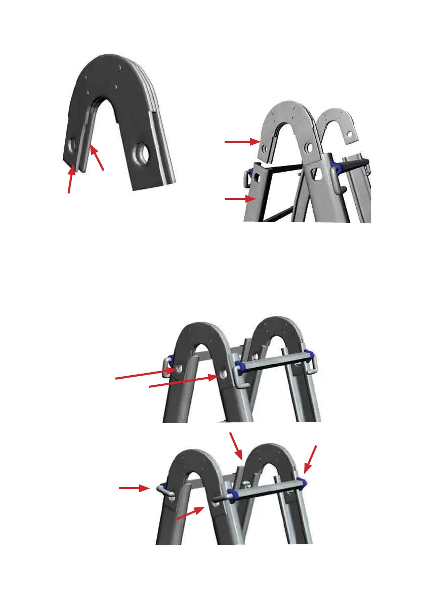
6. Make sure each Trestle Joint is
positioned with its plates both inside
and outside the ladder rails, joining
both bases to create an A-frame.
(See Figure F-6).
7. Check that the lock assembly holes of both
bases line up with the Trestle Joint holes,
then insert the lock assemblies.
(See Figure F-7a-7b).
5. Orientate the Trestle Joints so that the
Wide Plate slides over the inside of the
Ladder Rail and the Narrow Plate slides
over the outside of the Ladder Rail.
(See Figure F-5).
Trestle Joint
Narrow Plate
to the Outside
Narrow Trestle
Joint Plate
Wide Trestle
Joint Plate
Ladder Rail
Insert the four
Lock Assemblies
Align the Lock
Assembly Holes


 To Next Page