7
Figure A-8
To reset the ladder to the storage position,
use the above procedure but in reverse. The
hinges lock automatically at the A-frame
position to prevent damage to the ladder
or injury to the user. Take care not to
let the full weight of the ladder collapse
uncontrollably onto the hinge lock as you
change the ladder from the extension to
A-frameconguration.Disengagethehinge
locks in the A-frame position and return the
ladder to its storage position.
SAFETY PRECAUTION:
READ THE IMPRINT ON THE HINGE! "HINGE LOCK PINS MUST BE FULLY IN BEFORE
USE, FAILURE TO DO SO MAY RESULT IN INJURY"
SNAP AND
LOCK THE
LEG LOCK
ASSEMBLY
SECURELY IN
TO THE HOLE
BEFORE USE.
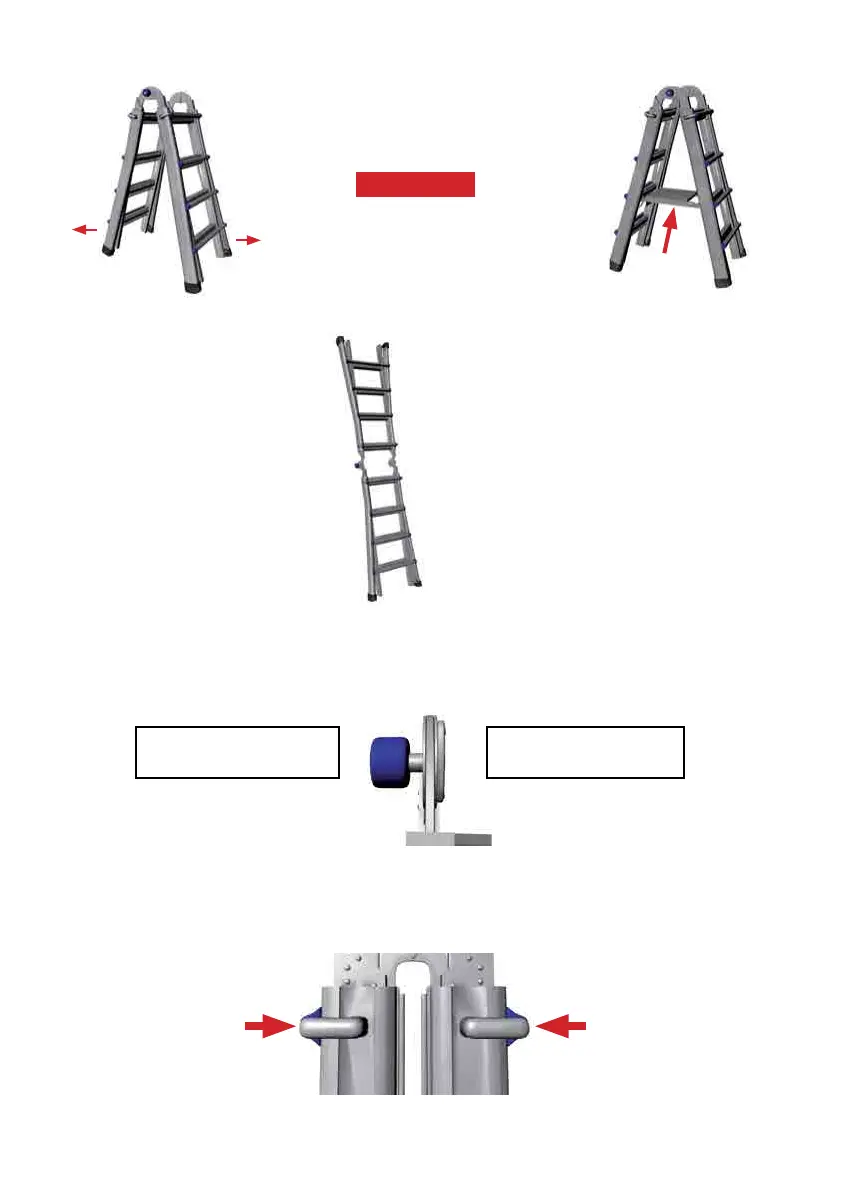
4. Next, change the ladder
into the extension posi-
tion by pushing straight
in on the palm buttons of
both hinges (See Figures
A-4 and A-5). Rotate
the ladder halves until
the hinge locks snap into
their locked position
(See Figure A-8).
HINGE LOCK PINS MUST
BE FULLY IN BEFORE USE
FAILURE TO DO SO MAY
RESULT IN INJURY
Figure B-1
B. Four Leg Lock Assemblies make up the second mechanical component of the ladder.
These allow you to adjust the height of the ladder.
(See Figure B-1).
Figure A-7
SNAP AND
LOCK THE
LEG LOCK
ASSEMBLY
SECURELY IN
TO THE HOLE
BEFORE USE.
Once the hinge lock pins snap into
place, insert the work platform as a
spreader to brace the ladder.
(See Figure A-7)
Refer to page 15 for more information
on how to insert the Work Platform.
(120KG MODEL ONLY)
2. Open the ladder by pulling the two
ladder halves apart until both hinge
lock pins snap and lock into the A-frame
position. (See Figure A-6).
Figure A-6
3. IMPORTANT
Insert Work
Platform