Do you have a question about the Thermador PSC366 and is the answer not in the manual?
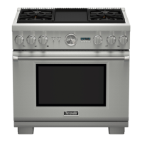
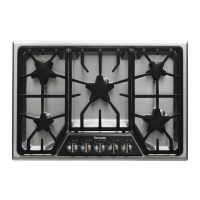
Overview of Thermador Professional Cooktops and their key features.
Essential steps to take immediately if a gas leak is detected.
Guide to choosing appropriate hood and blower models for installation.
Specifies minimum and maximum distances for hood installation above the cooktop.
Recommends a source of replacement air for ventilation systems.
Details required clearances and methods for mounting the cooktop to the countertop.
Specifies location for gas/electrical supply and overhead cabinet clearance.
Instructions for cutting cabinet openings and specific installation scenarios.
Procedures for safely removing packaging and components from the cooktop.
Guidance on positioning, leveling, and securing the cooktop in its opening.
Ensures correct gas type and verifies supply pressure meets specifications.
Details connecting the gas supply line, regulator, and shut-off valve.
Details power requirements, plug type, and receptacle specifications for connection.
Explains the mandatory grounding procedure and its importance for safety.
Step-by-step guide for attaching the low-back backguard or island trim.
Lists model numbers for low back and island trim accessories.
Procedures for testing burner operation, flame quality, and making adjustments.
Comprehensive checklist for installers to verify all installation steps are completed.
This document provides installation instructions for Thermador Professional Cooktops, including models P24WK, PSC364GD, PSC364GL, PSC366, PSC484GG, PSC486GD, PSC486GL, and PSC484WK. These cooktops are designed for professional-grade cooking and are available in 24-inch, 36-inch, and 48-inch widths, offering various configurations to suit different culinary needs.
The Thermador Professional Cooktops are high-performance gas cooking appliances designed for residential use, offering a range of burner configurations, griddles, and grills. They are intended for cooking and not for room heating. The 24-inch P24WK model features a powerful 30,000 BTU/HR wok burner. The 36-inch models (PSC364GD, PSC364GL, PSC366) come with either four sealed burners and a griddle, four sealed burners and a grill, or six sealed burners, respectively. The 48-inch models (PSC484GG, PSC486GD, PSC486GL, PSC484WK) offer configurations with four sealed burners, a griddle and a grill; six sealed burners and a griddle; six sealed burners and a grill; or four sealed burners and a 30,000 BTU/HR WOK. All sealed burners are rated at 15,000 BTU/HR, griddles at 15,000 BTU/HR, and grills at 18,000 BTU/HR. A unique feature of these cooktops is the intermittent/interrupted ignition device that cycles the two far-left surface burners on and off when set to the Extra Low® setting, providing precise low-temperature control.