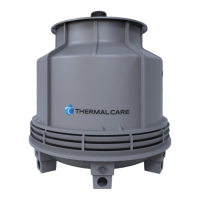
This document is an operation, installation, and maintenance manual for a THERMAL CARE Cooling Tower, specifically the FT Series.
Function Description:
The cooling tower is designed for the evaporative cooling of process water. It achieves this by utilizing evaporative fill material, a fan, a water distribution system, a shell, and a water collection basin. The primary purpose is to provide efficient heat transfer by exposing the process water to air, causing a portion of it to evaporate and thus cool the remaining water. The manual emphasizes that the cooling tower is intended for outdoor installation only.
Important Technical Specifications:
The manual provides structural steel base frame dimensions for various FT Series models:
- FT8220: Base frame dimensions are detailed in Figure 1, including measurements like 58 1/4", 63 1/4", 66 3/4", 29 7/8", 39 7/8", 36 7/8", 31 3/8", 41 7/8", 59 3/4", and a 56 3/4" bolt circle.
- FT8250: Base frame dimensions are detailed in Figure 2, including measurements like 59 3/4", 73 1/2", 70", 58 3/4", 45", 36 1/2", 25 1/4", 7 1/2", 6 1/2", 42 5/8", 61 1/4", 64 3/4", 68 1/4" (overall), 18 1/4", 78", 68 1/2" (overall), 51 3/4", and a 67" bolt circle.
- FT8260, FT8270, and TC8280: Base frame dimensions are detailed in Figure 3, including measurements like 73", 89 1/8", 85 5/8", 70 1/2", 52 13/16", 44 5/16", 29 1/8", 7 1/2", 6 1/2", 49 1/4", 74 1/2", 78", 81 1/2" (overall), 22 1/8", 63 1/2", 93 5/8", 84 1/8" (overall), and an 82 5/8" diameter bolt circle.
The manual also lists nominal flow rates and required inlet pressures for different models:
- FT8220: Operating Range: 60 to 200 gpm, Nominal Flow: 114 gpm, Inlet Pressure: 3 psi.
- FT8250: Operating Range: 90 to 340 gpm, Nominal Flow: 180 gpm, Inlet Pressure: 5 psi.
- FT8260: Operating Range: 180 to 500 gpm, Nominal Flow: 240 gpm, Inlet Pressure: 5 psi.
- FT8270: Operating Range: 180 to 500 gpm, Nominal Flow: 300 gpm, Inlet Pressure: 5 psi.
- FT8280: Operating Range: 180 to 500 gpm, Nominal Flow: 360 gpm, Inlet Pressure: 5 psi.
Electrical specifications include a maximum allowable voltage imbalance of 2%. The manual provides a formula for calculating percentage imbalance: %Imbalance = (Vavg – Vx) x 100 / Vavg, where Vavg = (V1 + V2 + V3) / 3 and Vx is the phase with the greatest difference from Vavg.
Water chemistry requirements for fill water are crucial for performance and longevity. Key parameters and their quality limitations are:
- Alkalinity (HCO3): 70-300 ppm
- Aluminum (Al): Less than 0.2 ppm
- Ammonium (NH3): Less than 2 ppm
- Chlorides (Cl): Less than 300 ppm
- Electrical Conductivity: 10-500µS/cm
- Free (aggressive) Carbon Dioxide (CO2): Less than 5 ppm
- Free Chlorine (Cl2): Less than 1 PPM
- HCO3/SO42-: Greater than 1.0
- Hydrogen Sulfide (H2S): Less than 0.05 ppm
- Iron (Fe): Less than 0.2 ppm
- Manganese (Mn): Less than 0.1 ppm
- Nitrate (NO3): Less than 100 ppm
- pH: 7.5-9.0
- Sulfate (SO42-): Less than 70 ppm
- Total Hardness (dH)k: 4.0-8.5
Usage Features:
The manual outlines detailed installation procedures for mechanical and electrical components.
- Foundation: The unit must be installed on a rigid, non-warping mounting pad, concrete foundation, or level floor, capable of supporting the full operating weight. It must be level within 1/4 inch over its length and width. For roof installations, the base should be elevated.
- Unit Location: A minimum of 60 inches of clearance is required between the cooling tower and any walls or obstructions, and between multiple towers. The location should allow for easy access for maintenance and servicing, and avoid "micro-climates" or obstructions to airflow. Fan noise and vibration transmission should also be considered.
- Fan Motor and Blade Assembly: Detailed steps are provided for installing the fan motor, fan blade, and sprinkler head assembly, including verifying fan pitch, securing components, and tightening bolts. For FT8220 & FT8250 models, the fan motor and blade ship unmounted. For FT8260 & FT8270 models, the fan motor, fan blade, and sprinkler head assembly ship unmounted. For FT8280 models, the fan motor, fan blade, and sprinkler head assembly ship uninstalled.
- Inlet Louver Installation: Instructions are given for installing inlet louvers for FT8220, FT8250, and FT8260-FT8280 models, which ship uninstalled. This involves aligning louvers with casing supports, drilling holes, and securing them with nuts and bolts.
- Piping: PVC piping and connections are not designed to support external piping weight. Field piping connections must be properly aligned to prevent stress fractures and leaks.
- Electrical Installation: All wiring must comply with local and national codes. Voltage must be within the specified range, and voltage imbalance must not exceed 2%. Proper phase sequence (ABC) is critical and must be checked before applying power.
- Start-Up Procedure: A qualified technician should perform the start-up. This includes flushing the basin, connecting main power, filling the water circuit, and trial fan operation. During trial fan operation, smooth operation, clearance between blades and tower, correct fan rotation (discharging air upwards), and amp draw within nameplate rating must be verified.
Maintenance Features:
The manual provides guidelines for operation and maintenance to ensure longevity and performance.
- Water Treatment Program: The use of untreated water can cause serious health hazards, including Legionella bacteria. A proper water treatment program is required to prevent biological contamination, corrosion, scale, and fouling.
- Fan Motor: The motor should reach full speed in less than five seconds. If vibration occurs, the fan should be shut off immediately, and mounting, fasteners, and blade balance checked. Frequent cycling of the motor should be avoided (total starting times not exceeding 12 starts per hour). When changing fan direction, a minimum of two minutes should be allowed before reenergizing.
- Water Distribution: Sprinkler arms should be checked for proper operation. If they slow or stop, water flow should be checked. Sprinkler arms and openings should be cleaned with a plastic bottlebrush and cleaning solution (pH 3.0 or greater).
- Seasonal Shutdown: For winter shutdown, running the motor for three hours a month is recommended to lubricate bearings and keep windings dry. The basin and fill should be inspected and cleaned if needed.
- Freeze Protection: To prevent freezing during intermittent shutdown or low loads in cold weather, an indoor auxiliary sump is recommended. If a remote sump is impractical, electric immersion heaters can be used in the basin. Freedom of fan rotation must be maintained, and the unit should not be operated if snow, ice, or obstructions interfere.
- Calculations: Formulas are provided for estimating:
- Evaporation Loss (GPM):
Range x GPM x .0008 (where Range is water in °F less water out °F, and GPM is gallons per minute through tower).
- Drift Loss (GPM):
GPM x .0002 (assuming 0.02% loss).
- Bleed-Off Rate: This is dependent on make-up water condition and desired concentrations, and should be calculated by the water treatment company.
- Number of Concentrations:
(Evaporation + Drift + Bleed-Off) / (Drift + Bleed-Off).
- Make-Up Water Required (GPM):
E + D + B (where E is Evaporative Loss, D is Drift Loss, and B is Bleed-Off Rate in GPM).