This document is an operation, installation, and maintenance manual for the Thermal Care Vactherm RV Temperature Controller.
Function Description
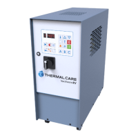
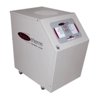
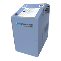
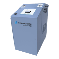
The Vactherm RV Temperature Controller is a packaged unit designed for circulating and controlling the temperature of a cooling fluid. It typically includes a fluid pump, an electric immersion heater, and a temperature control valve, all housed within a cabinet. The unit's primary purpose is to maintain a precise temperature for industrial processes, ensuring optimal performance and preventing equipment damage due to temperature fluctuations. It can be used with water or glycol solutions as the heat transfer fluid.
Important Technical Specifications
- Voltage Imbalance: Must not exceed 2% for three-phase systems to prevent motor overheating and failure.
- Cooling Source Temperature: Typically between 40°F (4.4°C) and 85°F (29.4°C).
- Cooling Source Supply Pressure: Generally between 25 psi and 50 psi. Units with a 300°F (149°C) operating range option require an inlet cooling source pressure of 75 psi.
- Maximum Total Pressure: If the total pressure (cooling source inlet pressure plus pump pressure) exceeds 150 psi, the pressure relief valve will open.
- Sound Pressure: The equipment can exceed 70 dBA sound pressure at 1 meter distance and 1 meter elevation when operating.
- Storage Temperature: Should not exceed 145°F (63°C) in a sheltered indoor area.
- Water Chemistry Requirements: Specific limitations for alkalinity (70-300 ppm), aluminum (less than 0.2 ppm), ammonium (less than 2 ppm), chlorides (less than 300 ppm), electrical conductivity (10-500 µS/cm), free (aggressive) carbon dioxide (less than 5 ppm), free chlorine (less than 1 PPM), HCO3/SO42- (greater than 1.0), hydrogen sulfide (less than 0.05 ppm), iron (less than 0.2 ppm), manganese (less than 0.1 ppm), nitrate (less than 100 ppm), pH (7.5-9.0), sulfate (less than 70 ppm), and total hardness (4.0-8.5 dHk).
- Glycol Solutions: Recommended glycol percentages vary with chilled water temperature: 5% for 45°F (7.2°C), 10% for 40°F (4.4°C), 15% for 35°F (1.7°C), 20% for 30°F (-1.1°C), 25% for 25°F (-3.9°C), and 30% for 20°F (-6.7°C). Industrial grade glycol specifically designed for heat transfer systems must be used.
- Pump Performance (60 Hz): A graph illustrates pump pressure (psi) versus flow (gpm), showing a decreasing pressure with increasing flow, from approximately 85 psi at 0 gpm to 15 psi at 24 gpm.
- Cooling Capacity: A graph shows cooling capacity (Btu/Hr x 1,000) versus ΔT Between Set Point and Cooling Water In (°F), indicating a linear increase in cooling capacity as the temperature difference increases, from approximately 8,000 Btu/Hr at 10°F ΔT to 50,000 Btu/Hr at 85°F ΔT.
- Heating Element Details: Diagrams illustrate various heating element configurations for different power ratings (6KW, 9KW, 12KW, 15KW, 18KW, 21KW, 24KW, 27KW, 30KW, 33KW, 36KW), showing how individual heating elements are connected in series and parallel.
- Control Board Details: The manual includes a diagram of the control board (AT89C51RD processor) with various connections (J5, J6, J7, J8, P1, P101, P102) and dip switch settings for controller functions like water/oil operation, heating stages, alarm outputs, and ventilation.
- Wiring Diagrams: High voltage and low voltage wiring diagrams are provided, detailing connections for power, motors, sensors, and control components.
Usage Features
- Digital LED Displays: The control panel features digital LED displays for showing various temperatures, status, and alarm conditions.
- Start/Stop Functionality: Dedicated buttons for starting and stopping the unit. An automatic fill sequence is initiated if the water level is low during startup.
- Temperature Adjust: A button to view and change the set point temperature, with Increase and Decrease buttons for adjustments.
- Date & Time Functions: Allows displaying and adjusting pump running hours, clock time, and day of the week.
- Automatic Start/Stop Timer: An optional feature to program daily start and stop times for the unit, with the ability to include or exclude specific days of the week.
- Deviation Alarm: Allows setting a temperature deviation limit. If the tank temperature exceeds this limit, an alarm horn activates, and a light illuminates. Includes a 45-minute delay after initial startup.
- Tank Temperature Display: A dedicated button to show the current tank temperature.
- Password Entry: A security feature to prevent unauthorized personnel from making changes to temperature or timer functions.
- Status Indicators: LED icons for pump status (green for on, yellow for overload), heating status (green for Heater 1 or Heater 2 on), cooling status (green for cooling valve open), low level alarm (yellow for low oil level), deviation alarm (green when active), and automatic timer status (green when active).
- Mold Draining Program: An automatic cool-down sequence to 105°F (40°C) before draining the mold, signaled by an alarm horn. A vacuum adjusting valve facilitates water removal from hoses and the mold.
Maintenance Features
- Preventive Maintenance Schedule: Suggested periodic maintenance includes:
- Once a Week: Check To Process temperature against Set Point (investigate if more than 5°F deviation), check pump discharge pressure (investigate deviations), and check pump for seal leaks.
- Once a Month: Repeat weekly checks, plus: check electrical connections for looseness or frayed wires, check incoming voltage (within 10% of design voltage), check amp draws for pump and heaters, check and clean heat exchanger inlet strainer, and check/replace oil as necessary.
- Once a Year: Repeat monthly checks, plus: carefully inspect and clean the heat exchanger for scale build-up.
- Troubleshooting Guide: A table listing common problems, possible causes, and remedies, such as replacing blown fuses, contacting the factory, resetting tripped breakers, checking power supply, cleaning lines, replacing defective components (motor, contactor, thermostat, heating element, solenoid valve, microprocessor), and cleaning/replacing probes.
- Water Chemistry Guidelines: Detailed requirements for fill water chemistry to prevent corrosion, scale, fouling, and biological contamination, emphasizing the need for chemical treatment and preventive maintenance.
- Glycol Usage Precautions: Warnings against using automotive grade glycol due to potential gelling, fouling, and material reactions, and a warning about ethylene glycol's flammability at higher temperatures.
- Safety Guidelines: Extensive safety precautions are highlighted throughout the manual, including warnings for hazardous voltages, hot oil/water/coolant under pressure, sharp edges, hot surfaces, flammable/explosive materials, and mandatory actions like wearing eye protection, protective gloves, ear protection, disconnecting power before maintenance, and proper grounding.