TSBC Instruction Manual Page 22 of 48
Installation
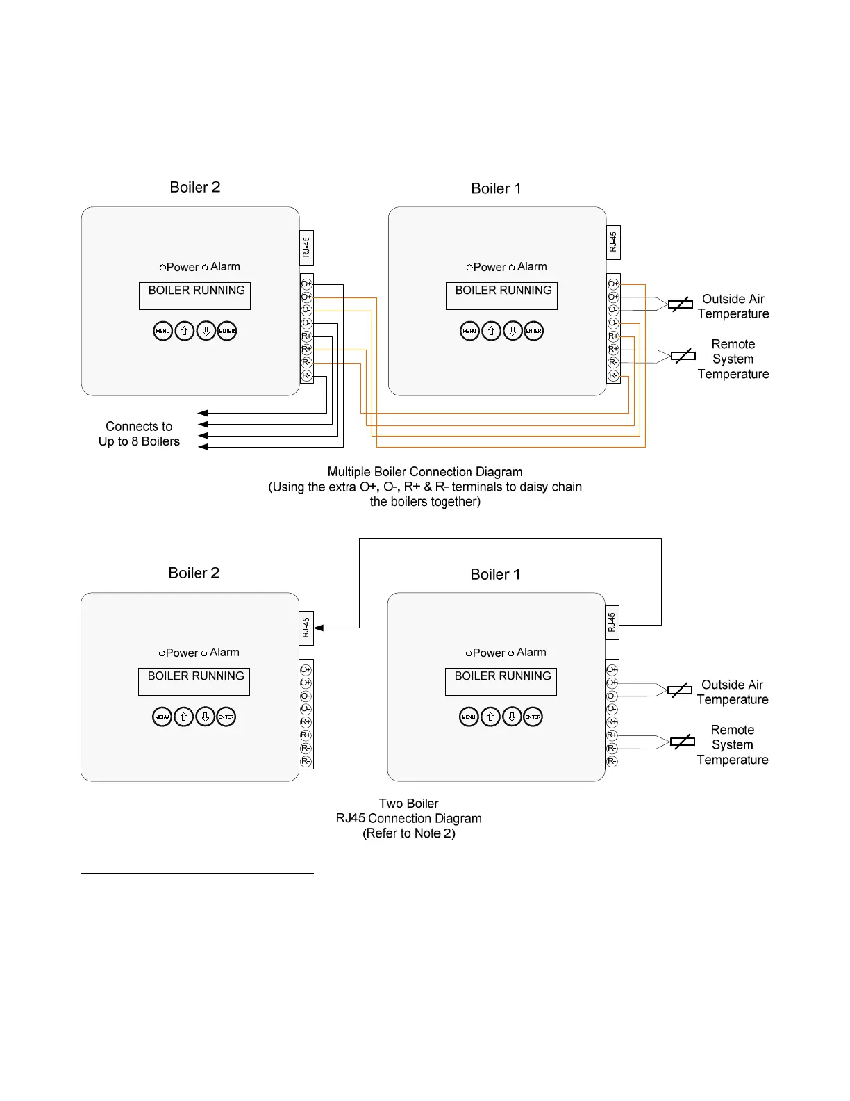
External Connections (Continued)
Outside Air and Remote System Temperature Sensor RJ45 Connection
All boilers may be connected to the remote system temperature (RST) and the outdoor air temperature (OAT) sensors.
Only one of each type sensor is needed for connections with up to eight boilers. The lead boiler is automatically
enabled to monitor the sensors. As the boiler lead rotates the sensor monitoring is automatically transferred to the new
lead boiler.
Notes
1. Used Only For Peer-To-Peer Network. When using Modbus Network wire Outside Air and Remote System sensor
to only one boiler.
2. Wiring from the Outside Air and Remote System Temperature sensors should use low impedance, shielded, twisted
pair wire and go directly to the terminals on any one boiler. Signal wiring should not be run in the same conduit with
power wiring. Wire shields may be connected to the common terminal (C) located on the same terminal block with
the outside air and remote system temperature connections.
3. The RJ45 sensor cables need to be a straight through type cable that connects each pin of the connector on one
end to it’s identical pin on the opposite end. Up to a total of three boilers may be connected using a RJ45 splitter.
When connecting more than three boilers, it is recommended, and may be more convenient, to use the extra O+,O-,
R+ & R- terminals to daisy chain the boilers together (eliminating the need for RJ45 cables and splitters and
reducing the loop impedance).

 Loading...