Section 2 - System Description
(10/08) 2 - 6
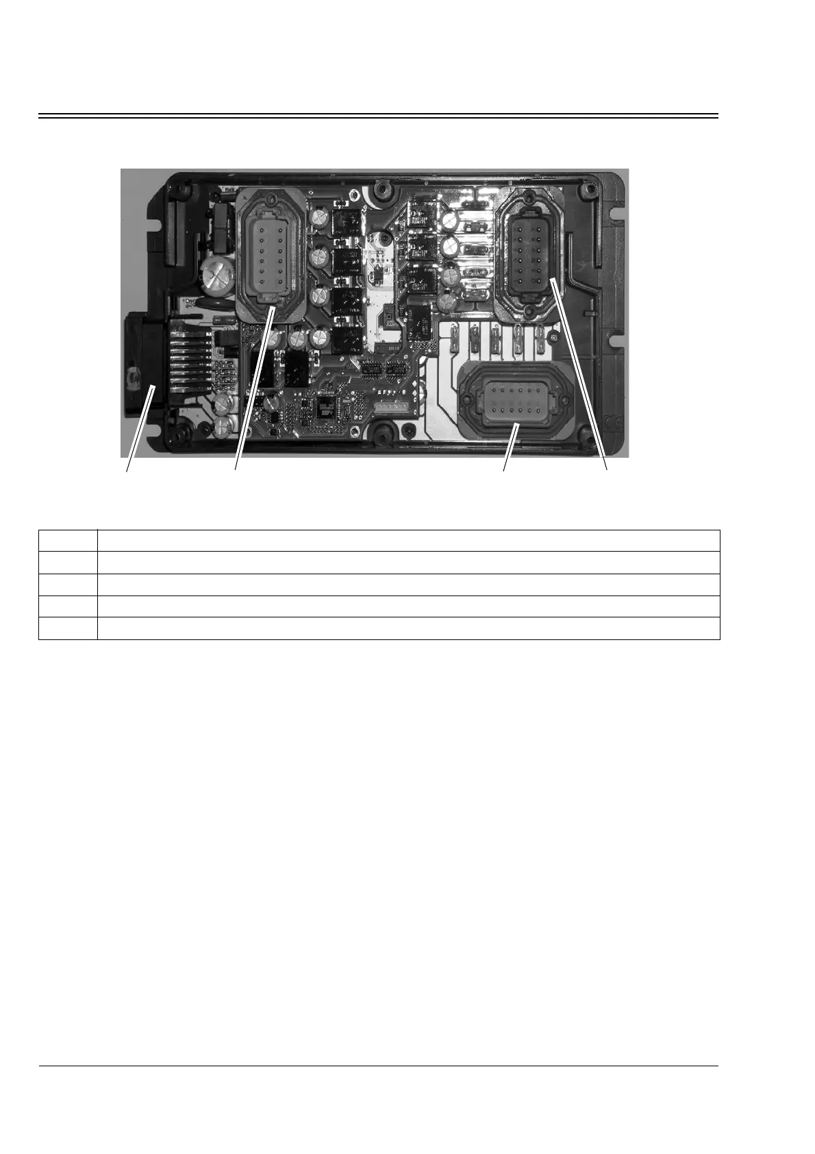
Figure 2-6 Internal Layout of a Platform 2 Electronic Control Module, showing PCB 1 and PCB 2
Electronic Control System
Components
The following sub-section describes the main
components of the Electronic Control System:
• Microprocessors
• PCB 1 and PCB 2
• Printed Circuit Board I/O Connectors
• System Fuses
• Printed Circuit Board Relays
•DSR μP Controller Inputs
•DSR μP Controller Outputs
Microprocessors
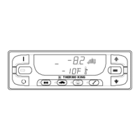
The controlling microprocessor in the In-cab
Control Box, and the slaved microprocessor(s)
in the ECM, are the heart of the DSR μP
Controller. The microprocessors accomplish the
following:
• In general, they monitor and control the
functioning of the refrigeration system
sensors, valves, switches, and motors
• The microprocessor(s) on PCB 1 and PCB 2
in the ECM receive input signals from the
controlling microprocessor in the In-cab
Control Box, and from sensors and electrical
components in the load compartment, and
provide output power signals to system
solenoid valves, motors, and heaters
Callout Description
1 Connector C-1, PCB 1
2 Connector C-1, PCB 2
3 Connector C-2, PCB 1
4 Connector C-2, PCB 2
 Loading...