EasyManua.ls Logo

Thermo Pride OH16-125 - User Manual

Thermo Pride OH16-125
18 pages
Print Icon
To Next Page IconTo Next Page
Loading...
MO-460
ECN 5577-MA 190924
ECM OPERATION MANUAL
FOR USE WITH MODELS:
OL16-125 OL20-151
OH16-125
: IF YOU DO NOT FOLLOW THE SAFETY PRECAUTIONS BELOW AND IN THIS MANUAL, A
FIRE OR EXPLOSION MAY RESULT CAUSING PROPERTY DAMAGE, PERSONAL INJURY, OR LOSS OF
LIFE.
DO NOT STORE OR USE GASOLINE OR OTHER FLAMMABLE VAPORS AND LIQUIDS IN THE VICINITY OF
THIS OR ANY OTHER APPLIANCE.
INSTALLATION AND SERVICE MUST BE PERFORMED BY A QUALIFIED INSTALLER, SERVICE AGENCY
OR THE GAS SUPPLIER. (REFERRED TO IN THESE INSTRUCTIONS AS A QUALIFIED HEATING
CONTRACTOR).
PLEASE READ THESE INSTRUCTIONS PRIOR TO INSTALLATION, INITIAL FIRING, AND BEFORE
PERFORMING ANY SERVICE OR MAINTENANCE. THESE INSTRUCTIONS MUST BE LEFT WITH THE
HOMEOWNER AND SHOULD BE RETAINED FOR FUTURE REFERENCE BY QUALIFIED SERVICE
PERSONNEL.
THERMO PRODUCTS, LLC.
BOX 237
DENTON, NC 27239
PHONE: 800-476-4328
MADE IN USA
Question and Answer IconNeed help?

Do you have a question about the Thermo Pride OH16-125 and is the answer not in the manual?

Overview

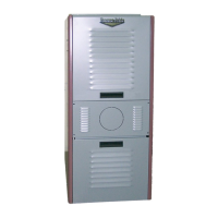
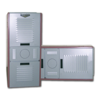
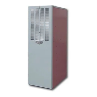
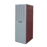
This document is an ECM (Electronically Commutated Motor) Operation Manual for Thermo Pride furnaces, specifically for models OL16-125, OL20-151, and OH16-125. It provides detailed information on the blower controller, wiring, operating modes, CFM tables, replacement parts, and troubleshooting.

Function Description

The ECM blower controller manages the operation of a multiple-speed ECM motor, which is responsible for circulating air in the furnace for heating, cooling, and fan-only modes. The control board receives inputs from the thermostat, humidistat, and limit switch, and based on these inputs, it regulates the blower speed and other furnace components.

Important Technical Specifications

Blower Controller Information:

  • Burner Harness Connector P1:
    • Pin 1: Limit switch connection.
    • Pin 2: 120 VAC Line connection.
    • Pin 3: Burner pilot contact.
    • Pins 4&5: 120 VAC Neutral connection.
    • Pin 6: Burner pilot contact.
    • Pins 7&8: From oil primary control.
    • Pin 9: Limit Switch Input (LSI).
  • Field Wiring to Burner:
    • Beckett Connections: Pilot (Tstat) - Yellow Wires, Neutral - White, Line - Red.
    • Riello Connections: T-stat terminals - White, Black.
  • Thermostat/Humidistat Connections (Single Stage):
    • "C": Common/ground.
    • "W": Thermostat call for heat.
    • "R": 24 VAC to thermostat.
    • "G": Thermostat call for fan.
    • "Y": Thermostat call for cool.
    • "DEHUM": Humidistat call for dehumidification (TXV systems ONLY).
  • Thermostat/Humidistat Connections (2-Stage Control):
    • "C": Common/ground.
    • "W1": T-Stat call for heat (low fire).
    • "W2": T-Stat call for heat (high fire).
    • "R": 24 vac to T-Stat.
    • "G": T-Stat call for fan.
    • "Y": T-Stat call for cool.
    • "DEHUM": Humidistat call for dehumidification (TXV systems ONLY).
  • ECM Control Outputs (6-pin P3 connector):
    • Pin 1: Speed Common.
    • Pin 2: Speed Output.
    • Pin 3: Motor CFM.
    • Pin 4: Blower Enable.
    • Pin 5: COOL Enable.
    • Pin 6: "R" Output.
  • Male Quick Connect Terminals:
    • "S1-3": 120 VAC Hot.
    • "N1-7": 120 VAC Neutral.
    • "EAC": Electronic Air Cleaner (120 VAC) connection.
    • "HUM": Humidifier connection (120 VAC).
    • "FAN": Fan On Signal.
    • "X": 24VAC from transformer.
    • "C": 24VAC common from transformer.
    • "CC": Compressor Contactor.
    • "CC_COM": Compressor Contactor Common.
  • Power Supplies: Line voltage between "S1" and "N1". 24 VAC Class II Transformer secondary voltage to X and C.
  • Limit Switch: 120VAC optically isolated input on P2-1 & 9.
  • Oil Burner Control: Dedicated contacts for T-T input of oil primary control. Rating: Class 2 - 24 VAC pilot duty @ 24 VAC (<200mA).
  • Oil Burner Power: Switched 120VAC power from LIMIT switch through board between Pins 1&2 of P1.
  • Compressor Contactor: Switched 24VAC output. Rating: Class 2 - 24 VAC pilot duty @ 24 VAC (<200mA).
  • EAC Output: 120VAC output, energized whenever fan motor is energized.
  • Humidifier Output: 120 VAC output, pass-through connection from P1-7. Controlled by humidistat.
  • Blower Delay Times (DIP Switch 2, Table 1):
    • ON Delay (Sec): 30, 60, 120 (Factory Set), 240.
    • OFF Delay (Min): 2, 4, 6 (Factory Set), 8.
  • CFM Tables: Detailed tables for Cooling Speeds (Tons, COOL, LOW, DEHUM CFM) and Heating Speeds (SW1 switches, °F Rise, CFM) for OL16/OH16 and OL20 models. Six dip switches (SW1) select speed values for heat, cool, fan, and dehumidification.

Usage Features

  • Operating Modes:
    • Standby Mode: All outputs off, waiting for thermostat demand. Continuously monitors thermostat inputs and limit switch.
    • Fan Mode ("G" call): Operates at a "Low" speed determined by SW1 positions 4-6. Overridden by Heat or Cool modes after their turn-on delays.
    • Cooling Mode ("Y" call): Energizes "CC" terminal (if heat mode not active or anti-short cycle delay not in effect). Blower ramps up to "COOL" speed (SW1 positions 4-6) after a 10-second delay. After call is satisfied, "CC" de-energizes, cooling off delay (45 seconds) starts, then blower ramps to zero.
    • Dehumidification Operation ("DEHUM" call): If active during Cool Mode, blower speeds are reduced, selected from DEHUM column of CFM Tables. Only for systems with TXV.
    • Anti-Short Cycle Operation: Ignores cooling calls for four minutes after termination of any cooling call, also in effect at power-up.
    • Heat Mode ("W" call): Energizes "T-T" terminal (if cool mode not active), starts blower on delay (SW2 positions 1-2). After delay, blower ramps to heat speed (SW1 positions 1-3). 2-Stage control uses W1 (low fire, 15 min) and W2 (high fire). Counterflow units run at low speed shortly after burner on. After call is satisfied, "T-T" de-energizes, blower off delay (SW2 positions 3-4) starts, then blower ramps to zero.
  • Motor Blower Speed: "G" call for Low speed, "W" call for Heat speed, "Y" call for Cool speed. Priority logic for simultaneous "Y" and "W" calls.
  • DIP Switch Configuration: Allows customization of blower on/off delays and speed values for various operating modes.

Maintenance Features

  • Diagnostic Features:
    • Green Input Status LEDs: Located below "Y", "W", "G", and "DEHUM" inputs, light up to indicate presence of these signals.
    • Red Board Status LED: Lights when a valid input signal is recognized and stays lit until all valid signals are removed, indicating board functionality. Flashes rapidly if 120VAC is missing from the LIMIT switch, indicating a High LIMIT switch issue.
  • Troubleshooting Charts: Provides a systematic guide for diagnosing ECM blower motor malfunctions, including symptoms, causes, and procedures.
  • General Guidelines to Troubleshooting GE ECM – Driven Systems:
    • Safety Precaution: Disconnect power before servicing. Wait 5 minutes after disconnecting power before opening motor.
    • Common Symptoms & Solutions: Addresses issues like motor not starting, erratic operation, noise, and constant airflow.
    • "DO" and "DON'T" Guidelines: Best practices for motor, controls, wiring, static pressure, filter maintenance, ductwork design, and equipment sizing.
    • Moisture Check: Guidelines for preventing and identifying moisture-related issues, including connector orientation, drip loops, condensate drain, and checking for leaks.
    • Comfort Check: Recommendations for proper airflow settings, low static pressure, continuous-fan CFM, and thermostat placement.
  • ECM – PSC Replacement (Emergency Only): In an emergency, a defective ECM motor can be temporarily replaced with a PSC motor of similar horsepower. Wiring instructions are provided for this temporary solution until a replacement ECM motor can be obtained.
  • Replacement Parts: Lists specific part numbers for ECM Motor, Control Board, Motor Power Harness, Motor Control Harness, Burner Harness, Transformer, and Power Choke for OL16, OL20, and OH16 models.

Safety Warnings:

  • "AWARNING: IF YOU DO NOT FOLLOW THE SAFETY PRECAUTIONS BELOW AND IN THIS MANUAL, A FIRE OR EXPLOSION MAY RESULT CAUSING PROPERTY DAMAGE, PERSONAL INJURY, OR LOSS OF LIFE."
  • "DO NOT STORE OR USE GASOLINE OR OTHER FLAMMABLE VAPORS AND LIQUIDS IN THE VICINITY OF THIS OR ANY OTHER APPLIANCE."
  • "INSTALLATION AND SERVICE MUST BE PERFORMED BY A QUALIFIED INSTALLER, SERVICE AGENCY OR THE GAS SUPPLIER. (REFERRED TO IN THESE INSTRUCTIONS AS A QUALIFIED HEATING CONTRACTOR)."
  • "AWARNING: TURN OFF THE ELECTRICAL POWER to the furnace before attempting to disconnect blower wiring."
  • "AWARNING - APPLYING 240VAC LINE INPUT WITH PIN 1 TO PIN 2 JUMPER IN PLACE WILL PERMANENTLY DAMAGE UNIT."

Thermo Pride OH16-125 Specifications

General IconGeneral
BrandThermo Pride
ModelOH16-125
CategoryFurnace
LanguageEnglish

Related product manuals