Do you have a question about the Thermo Pride OH6FA072D48B and is the answer not in the manual?
Explains the digits and their meaning in the furnace model number.
Provides example model numbers for illustration.
Important warnings regarding furnace operation, maintenance, and safety.
Warnings about annual service, reinstallation, hazardous voltage, and fan blades.
Installer must inform user on operation, hazards, and warnings.
Considerations for unit size, location, and material definitions.
Ensuring adequate air for combustion and ventilation.
Connecting to an adequate chimney and proper sizing.
Measures to prevent condensation in the chimney to avoid corrosion.
Guidelines for chimney height and termination points.
Proper connection of the vent connector pipe to the chimney.
Clearances required for flue pipes passing through combustible materials.
Information on sidewall venting and flue elbow rotation.
Duct system must be sized and installed by qualified personnel.
Formulas for determining CFM requirements for heating and cooling.
Methods for sizing ductwork based on velocity and pressure drop.
Instructions for mounting the air filter externally to the furnace.
Warning against relocating or replacing safety controls.
Requirement to install the limit control during unit installation.
Steps for installing the burner, including retainer usage.
Details on Beckett and Riello burner models and their applications.
Information on nozzle capacity and Riello 2-stage burner specifications.
Adherence to codes and recommendations for pipe/fittings.
Installation of shutoff valve, unions, and sealant.
Recommendations for using copper tubing and avoiding kinks.
Recommendation and maintenance for the oil filter assembly.
Appliance must be grounded per codes; all wiring must conform.
Checking electrical connections, wiring diagrams, and sizes.
Setting the thermostat anticipator for proper heating control.
Tables for selecting heating speed based on BTUH and static pressure.
Tables for selecting heating speed based on BTUH and static pressure.
Tables for 2-stage heating air flow and temperature rise.
Tables for selecting cooling speed based on tonnage and airflow.
Tables for selecting cooling speed based on tonnage and airflow.
Data for setting blower speed based on static pressure and temperature rise.
Definitions of control terminals and field wiring connections.
Descriptions of controller inputs (thermostat, limit) and outputs (blower, burner).
Descriptions of standby, fan, cooling, dehumidification, and heat modes.
Steps for initial startup, including safety warnings and oil line purging.
Procedures for adjusting burner combustion for efficiency and safety.
Adjusting heat input rate via pump pressure or nozzle replacement.
Setting and verifying the supply air temperature rise.
Final checks of controls and operation before placing system into service.
Guidelines for oil supply, valve operation, and combustion air.
Areas to inspect and general cautions for user safety.
Steps for starting the burner and filter cleaning/location procedures.
Installer must inform homeowner about manual, controls, and operation.
Encourage annual inspection and warn of warranty voiding.
Safety precautions for qualified contractors during service.
Inspection of vent terminal, burner, combustion chamber, and oil filter.
Detailed steps for qualified personnel to clean the heat exchanger.
Checks for blower operation, electrical system, and controls.
Procedure for filter replacement and steps for extended shutdown.
Troubleshooting is for trained personnel; familiarize with procedures first.
Using control module LEDs and checking the cad cell for diagnostics.
Flow charts to help identify and resolve operational issues.
Fields for customer name, address, and heating system details.
Parameters to be tested for combustion and efficiency.
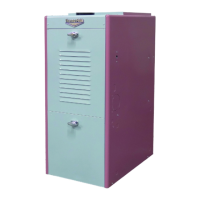
List and diagrams of replacement parts for OH6FA072D series furnaces.
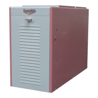
List and diagrams of replacement parts for OH8FA119D series furnaces.
Wiring diagrams including ladder and schematic for OH6FA072D48 PSC.
Wiring diagrams including ladder and schematic for OH6FA072DV4 ECM.
Wiring diagrams for OH6FX072DV4 ECM 2-Stage furnace.
Coverage for parts (10 years) and heat exchanger (lifetime).
Conditions required for warranty coverage, including registration.
Actions that will void the warranty, such as non-compliance.
| Brand | Thermo Pride |
|---|---|
| Model | OH6FA072D48B |
| Category | Furnace |
| Language | English |




 Loading...