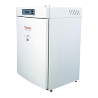
This document describes the Precision High Performance Incubators - Double Door, Series 2076, manufactured by Thermo Scientific. These incubators are designed for general incubating and paraffin embedding applications, offering robust construction and precise temperature control.
Function Description:
The Thermo Scientific High Performance Incubators are designed to maintain a controlled internal environment suitable for various laboratory applications, particularly general incubating and paraffin embedding. The units feature a PID microprocessor-based controller for accurate temperature management and an over-temperature safety thermostat to prevent overheating in case of primary control failure. A status lamp above each control indicates when the respective control is supplying power to the heaters. The double-door design, with an inner tempered glass door, allows for observation of chamber contents without significantly disturbing the internal environment. Slide-out shelving provides flexibility for user requirements.
Models PR205075M, PR205070M, and PR205070MCN additionally offer mechanical convection. These models incorporate a blower and plenum design to circulate air within the chamber, facilitating rapid temperature and uniformity recovery after door openings. The units are constructed with heavy-gauge steel cabinets featuring a powder-coated finish for durability and easy cleaning. The interior walls are made of stainless steel, which helps to distribute warm radiant heat evenly throughout the chamber. Heaters are in direct contact with the chamber walls, enabling close temperature control and quick recovery. This design also minimizes temperature gradients and maximizes the working area within the chamber. Two grounded 3-prong convenience outlets are installed in all models, which are built for either 120 VAC or 240 VAC power requirements.
Important Technical Specifications:
-
Models Covered:
- PR205075G (6877): 11.2 cu ft, 120V, Gravity Convection
- PR205070G (6873): 11.2 cu ft, 240V, Gravity Convection
- PR205070GCN (6874): 11.2 cu ft, 240V, Gravity Convection
- PR205075M (6878): 11.2 cu ft, 120V, Mechanical Convection
- PR205070M (6875): 11.2 cu ft, 240V, Mechanical Convection
- PR205070MCN (6876): 11.2 cu ft, 240V, Mechanical Convection
-
Electrical Requirements:
- PR205075G / PR205075M: 120V, 60Hz, 8.3 Amps, 1000 Watts (2 electrical outlets, 120V, 500W total load)
- PR205070G / PR205070M / PR205070GCN / PR205070MCN: 230/240V, 50/60Hz, 5.0 Amps, 1200 Watts (2 electrical outlets, 240V, 720W total load)
-
Temperature Range: Slightly above ambient to 65°C.
-
Shipping Weight: 215 lbs (98 kg).
-
Unit Dimensions:
- Inside: 37"W x 21"D x 25"H (94 x 53 x 64 cm)
- Outside: 40.5"W x 25"D x 34.5"H (103 x 64 x 88 cm)
-
Usable Volume: 11.2 cu. ft.
-
Shelves: 6 provided.
-
Shelf Area: 13.8 sq. ft.
-
Environmental Conditions:
- Operating: 15°C to 40°C; 20% to 80% RH, non-condensing.
- Installation Category: II (overvoltage) in accordance with IEC 664.
- Pollution Degree: 2 in accordance with IEC 664.
- Altitude Limit: 2,000 meters.
- Storage: -25°C to 65°C, 10% to 85% relative humidity.
Usage Features:
- Control Panel: Features a POWER SWITCH (rocker switch, lit when ON), CONTROL STATUS LAMP (lit when power is supplied to heater), PROGRAMMABLE CONTROLLER (maintains chamber temperature, displays chamber or set point temperatures), OVER-TEMPERATURE STATUS LAMP (lit during over-temperature condition or if thermostat is set too low), and OVER-TEMPERATURE THERMOSTAT (hydraulic thermostat set by operator as a safety backup).
- Start-Up: Involves rotating the over-temperature thermostat stem clockwise, plugging in the unit, and pressing the power switch to ON.
- Setting Over-Temperature Thermostat: After reaching the set point, rotate the over-temperature thermostat stem counterclockwise until its status lamp lights, then clockwise approximately 5° past the point where the lamp turns off. This ensures the thermostat controls heaters only above the controller set point.
- Temperature Controller Self-Test: Upon power-up, the controller displays "8888" with decimal points and the heat ON indicator, then blanks for 2 seconds before showing chamber temperature.
- Heat ON Indicator: This lamp illuminates when the chamber heater receives power, typically flashing when the chamber is at the set point.
- Set Point Adjustments: The temperature set point can be viewed or changed by pressing and holding the "STAR" (*) key and using the UP or DOWN arrow keys. A minimum of 30 minutes is recommended for stabilization after adjustment.
- Autotune Program: Automatically adjusts controller parameters for optimal temperature control. Not strictly necessary for initial setup but recommended if temperature appears unstable. The procedure involves entering program mode, navigating to "At.SP", and allowing the program to run until the display shows only the chamber temperature.
- Temperature Calibration: Requires placing a calibrated thermometer in the chamber, allowing stabilization, noting the thermometer reading, and then adjusting the controller's Zero value using a specific sequence of key presses to match the thermometer reading within ±0.5°C.
Maintenance Features:
- General Checks: Periodically verify that both control panel status lamps are functioning as described in the operation section. If the over-temperature status lamp remains lit after recalibration, refer to the troubleshooting section.
- Cleaning:
- Immediately clean spills using only soap or mild detergent and water with a soft cloth. Avoid abrasives on the glass inner door.
- Wipe the exterior with a soft damp cloth to remove dust and fingerprints.
- Care and Cleaning of Stainless Steel:
- Warning: Electrolysis can damage stainless steel. Avoid leaving objects directly on the surface that trap moisture and create oxygen-starstarved conditions.
- Water Quality: Distilled water is recommended. If using very pure distilled water, add 2 to 40 ppm (20 to 40 mg/liter) disodium phosphate or sodium bicarbonate to achieve a pH of 7 to 9. Alternatively, use clean, aerated soft tap water with total solids < 500 PPM. Avoid 18 meg-ohm deionized water; if it's the only source, mix 50/50 with regular tap water.
- pH Factor: Regularly check pH. If pH <6.0, add disodium phosphate to raise it to 7-9. Sodium carbonate or bicarbonate can be used but may form scale. If pH >10.0, add sodium bisulfate to lower it to 7-9. Avoid harsh alkalines or acids.
- Chemicals to Avoid: Never use Aqua regia, Ferric chloride, Iodine, or Sodium azide on stainless steel. Immediately remove any chemical spills, especially those listed, and clean with mild soapy water followed by a clean water rinse.
- Cleansing Agents: Anti-fungal and anti-bacterial additives are permissible if the pH of the aqueous solution remains between 7 and 9 and they are confirmed not harmful to stainless steel. For stubborn stains, use a plastic light-duty cleansing pad and rub gently with the metal grain.
- Stubborn Stains/Scale Removal: Can use "scale removers" for coffee makers/humidifiers, a 15-35% phosphoric acid solution (allow to soak, then rinse), citric acid-based cleaners, or bathroom tub/tile cleaners. Always follow manufacturer's directions, minimize scrubbing, and follow with a clean water rinse. Air dry.
- Disinfecting Materials: Glutaraldehyde and alcohol are effective. Note that local city codes may regulate the use and disposal of these chemicals.
- Troubleshooting: A guide is provided for common issues such as power switch lamp not lighting, unit not heating, or convenience outlets not powered. Emphasizes disconnecting power and referring servicing to qualified personnel.
- Heater Replacement: Heaters are not replaceable; contact Technical Services for assistance.
- Thermostat Replacement: Involves unplugging the unit, removing the top cover, detaching the thermostat from its mounting bracket, disconnecting wiring, removing the back cover to access the thermostat bulb, sliding the bulb out, and then installing the new thermostat by reversing the steps.
- Switch or Status Lamp Replacement: These are snap-in mounting types. Involves unplugging the unit, removing the top cover, disconnecting leads, pushing the switch out from the back, sliding the lamp body sideways to remove the lens, and then reversing the procedure for installation.
- Replacing Temp Controller: Involves placing the ON/OFF switch in OFF, unplugging the incubator, firmly gripping and pressing the controller bezel to release tabs, slowly pulling the controller from the housing, then carefully sliding the new factory-configured controller into the housing until tabs lock, plugging the incubator in, and placing the ON/OFF switch in ON.
- Ordering Procedures: Requires referring to the Specification Plate for model, serial, and series numbers. All parts can be ordered from a Thermo Scientific dealer or factory. A "Return Materials Authorization" (RMA) number is required for returning any materials, and contaminated products will not be accepted.