c. Operation of the CO2
Gas Guard
With the Gas Guard in operation, the incubator will use the
gas supplied by the tank connected to Inlet #1 until the pressure
drops below 10 psig (0.690 bars). At this time, the Gas Guard
automatically switches to the gas supplied through CO
2 Inlet
#2.
In addition, the incubator automatically changes the Tank
Select in Configuration mode from 1 to 2 to indicate that the
incubator is now using gas supplied through Inlet # 2. If the gas
supply to Inlet #1 is replenished, the incubator will continue to
operate using the gas supplied through Inlet #2 unless the oper-
ator changes the Tank Select from #2 to #1 through
Configuration mode. Refer to Section 4, Configuration.
Audible and visual alarms occur on the control panel when
the gas guard switches from one supply to the other. The audi-
ble alarm sounds until the operator presses the Silence key on
the control panel. The visual alarm in the Message Center will
read “Tank 1 Low” while the audible alarm is sounding, but the
message will be removed when the
operator presses the Silence key.
However, the ‘Tank Low’ indicator
on the control panel will stay light-
ed until the condition is resolved.
The unit will operate normally.
Both the audible and visual alarms described
above do not ring back after the Silence key is
pressed.
If the Gas Guard system does not detect an adequate gas
supply at CO
2 Inlet #1 or Inlet #2, a visual and audible alarm
will again occur on the control panel. The visual alarm in the
Message Center will read “Tank 1&2 Low”. The audible alarm
will continue to ring until the Silence key is pressed. The audi-
ble alarm will ring back every 15 minutes after the alarm is
silenced if the Gas Guard continues to detect that both gas sup-
ply pressures are below 10 psig (0.690 bars).
9.3 Datalogger (P/N 201912)
1. To install the datalogger sensor, locate the sensor and
cable in the bottom of the incubator chamber.
2. Insert the grommet provided into the only round hole in
the side of the diffuser pan.
3. Then route the sensor through this grommet, from the
bottom of the diffuser pan.
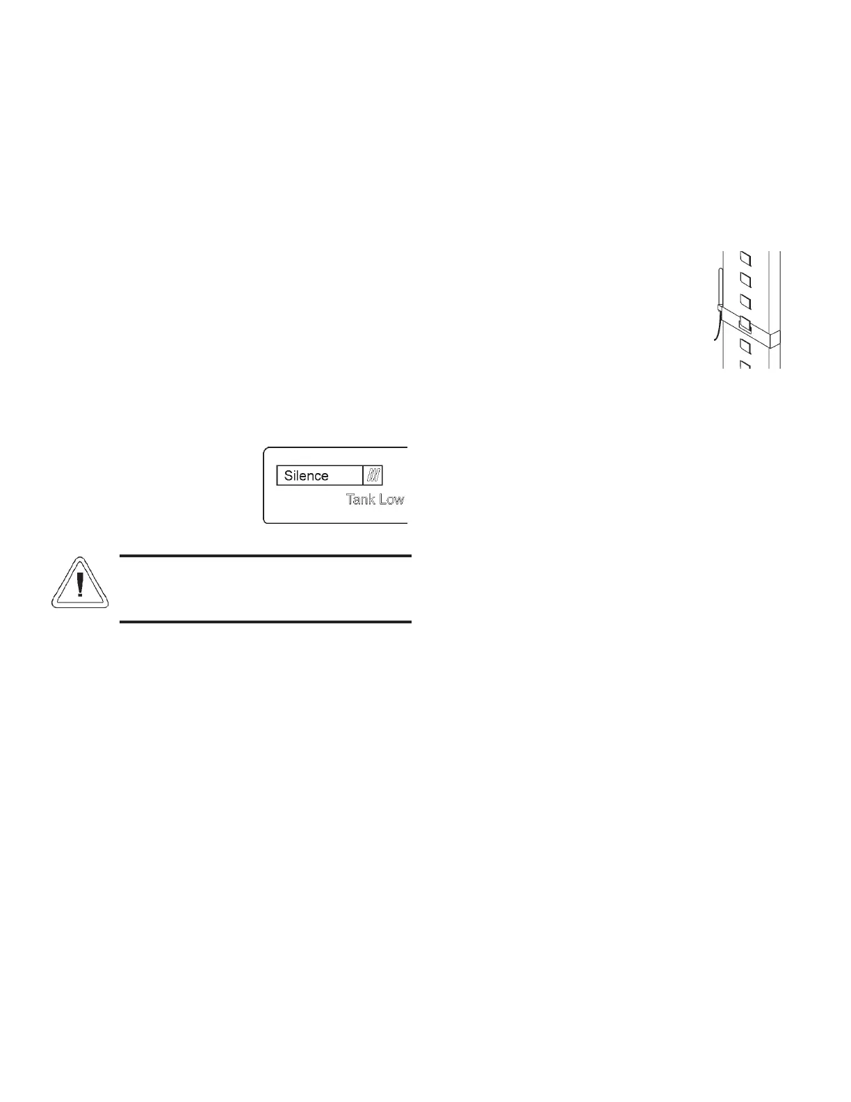
4. Place the datalogger sensor in the
desired location or use the clip
provided. See Figure 9-8 (clip
shown on pilaster).
5. See the ELPRO operating manual
for settings.
Steri-Cult Incubator ____________________________________________________________________Factory Options
9 - 3
Figure 9-8
Figure 9-7