MULTISKAN
RC
and
M
)
Write pulse for SRAM,
EEPROM and P/O circuits.
RD
(Read) Read puls
EEPROM,
circuits.
ALE AEEis usedto set the lower
(Address bits (0-7) of address for
Latch circuit
Dl
1
(Octal transpa-
Enable)
rent latch).
ALE
is also,
togetherwith
CPU
READY
signal, used tocreate aclock
signal oF3.042
MHz
which
is lead to the CLK input of
the CPU.
CLK (Clock) Clocksignal forVO circuirs.
10
Select read/write operation
to be either inputloutput or
memory oriented, input/
output
HIGH
active
RE
Reset output for peripheral
circuits,
HIGH
active
SO,
S1
Not used
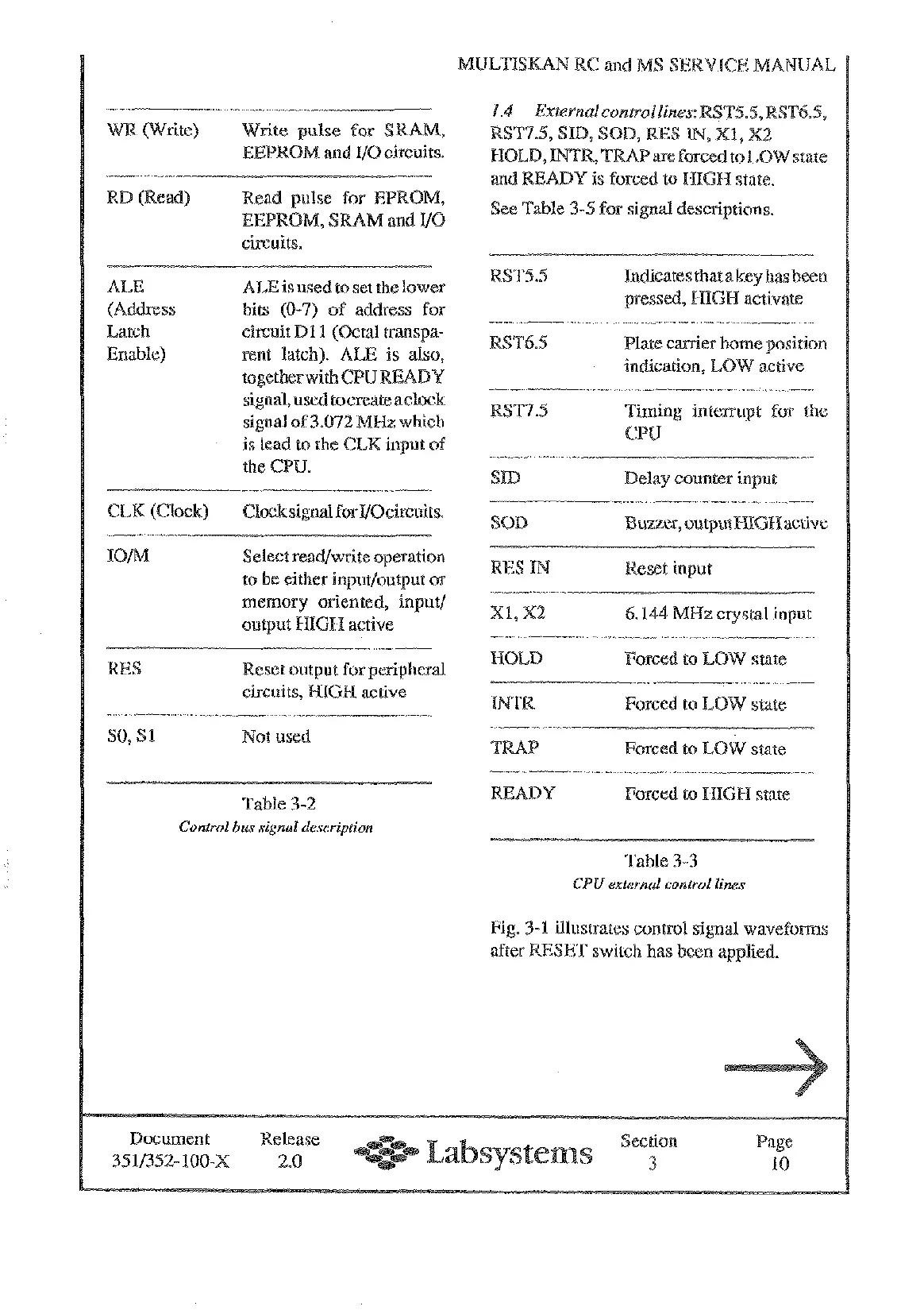
ee Table 3-5 for signal descbiptions.
RSTS.5 hdicates that a key has been
pressed,
HIGH
activate
RST6.5 Plate carrier home position
indication, LOW active
'ming interrupt for the
PU
SID
Delay counter input
OD
Buzzer, outputPT1GR active
ES
IN
eset input
XI,
X2
6.144
MHz
crystal input
HOED
Forced to
LOW
state
Forced to LOW state
Table
3-2
READY Forced to
HIGH
state
Control
bus
signal description
Table 3-3
CPU
external control lines
Fig.
3-1
illustrates control signal wavefoms
ESET
switch has been applied.
Document Release Section age
e
351/352-100-X 2.0
3 10
Artisan Technology Group - Quality Instrumentation ... Guaranteed | (888) 88-SOURCE | www.artisantg.com