MblLTlSKAld
a@
and
S
SERVICE
MANUAL
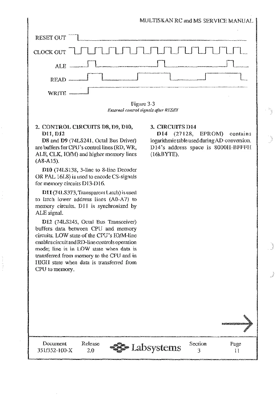
RESET OUT
CLOCK
OUT
ALE
Figure
3-3
Exter~lal
control
signals
after
RESET
(74LS241, Octal
CPU's
control lin
ALE,
CLK,
TOM)
and higher memory lines
(A84.15).
(74LS138, 3-fine to 8-line Decoder
OR PAL 16L8) is used to encode CS-signals
for memory circuits D13-Di6.
Dl1
(74LS373,Transpaent Latch) is used
to latch lower address lines
(AO-A7)
to
memory circuits.
Dl1
is synchronized by
ALE signal.
DU
(74LS245, Octal us Transceiver)
buffers data between CPU and memory
circuits. LOW state of
the
GPU's
ION-line
enablescircuit and RD-line controls operation
mode; line
is
in
LOW state when datd
is
transferred from memory to the
CPU
and in
HIGH
state when data
is
transfenred from
CPU to memory.
logarithmic table used
D14's address spa
Document Release
Section Page
3511352- 100-X 2.0
3
11
Artisan Technology Group - Quality Instrumentation ... Guaranteed | (888) 88-SOURCE | www.artisantg.com