4N
3269
page
6/17
2.
WORKING PRINCIPLE
RECTlF IER
INRUSH
FZ CURRENT
LIMIT
LINEVOLTAGE
SWITCHING
CIRCUIT
"OPTO"
BIN
CONTROL
CONTROL
(2
BIT)
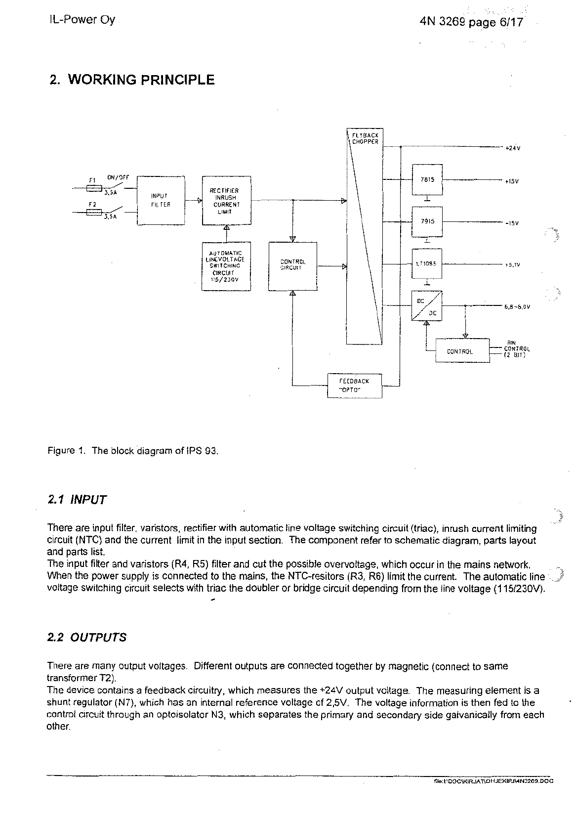
Figure
1.
The block diagram of IPS 93.
2.7
INPUT
There are input filter, varistors, rectifier with automatic line voltage switching circuit (triac), inrush current limiting
circuit (NTC) and the current limit in the input section. The component refer to schematic diagram, parts layout
and parts list.
The input filter and varistors (R4, R5) filter and cut the possible overvoltage, which occur in the mains network.
When the power supply is connected to the mains, the NTC-resitors (R3, R6) limit the current. The automatic line
voltage switching circuit selects with triac the doubler or bridge circuit depending from the line voltage
(1
151230V).
4
2.2
OUTPUTS
There are many output voltages. Different outputs are connected together by magnetic (connect to same
transformer T2).
The device contains a feedback circuitry, which measures the +24V output voltage. The measuring element is a
shunt regulator (N7), which has an internal reference voltage of 2,5V. The voltage information is then fed to the
control circuit through an optoisolator N3, which separates the primary and secondary side galvanically from each
other.
file
I
\DOC\KIRJAT\OHJEKIRJWN3269
DOC
Artisan Technology Group - Quality Instrumentation ... Guaranteed | (888) 88-SOURCE | www.artisantg.com