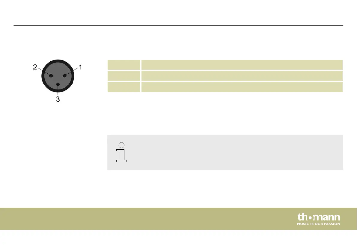
Two three-pin XLR sockets serve as DMX outputs. The following gure and the table show the
pin assignment of the sockets.
1 Ground
2 DMX data (–)
3 DMX data (+)
For each function of a DMX device (e.g., colour, brightness, ash interval, etc.), a dedicated
control channel is provided. The control channels can be assigned to a block of channel faders
on the light control console.
The DMX address denes the number of the rst DMX control channel of a device (1 –
512).
DMX outputs
DMX address and control chan‐
nels
Installation
DMX Invader 1024 NET
19

 Loading...