2-45
DRIVE MOTOR 2.12
C2320
C2321
C2322
C2324
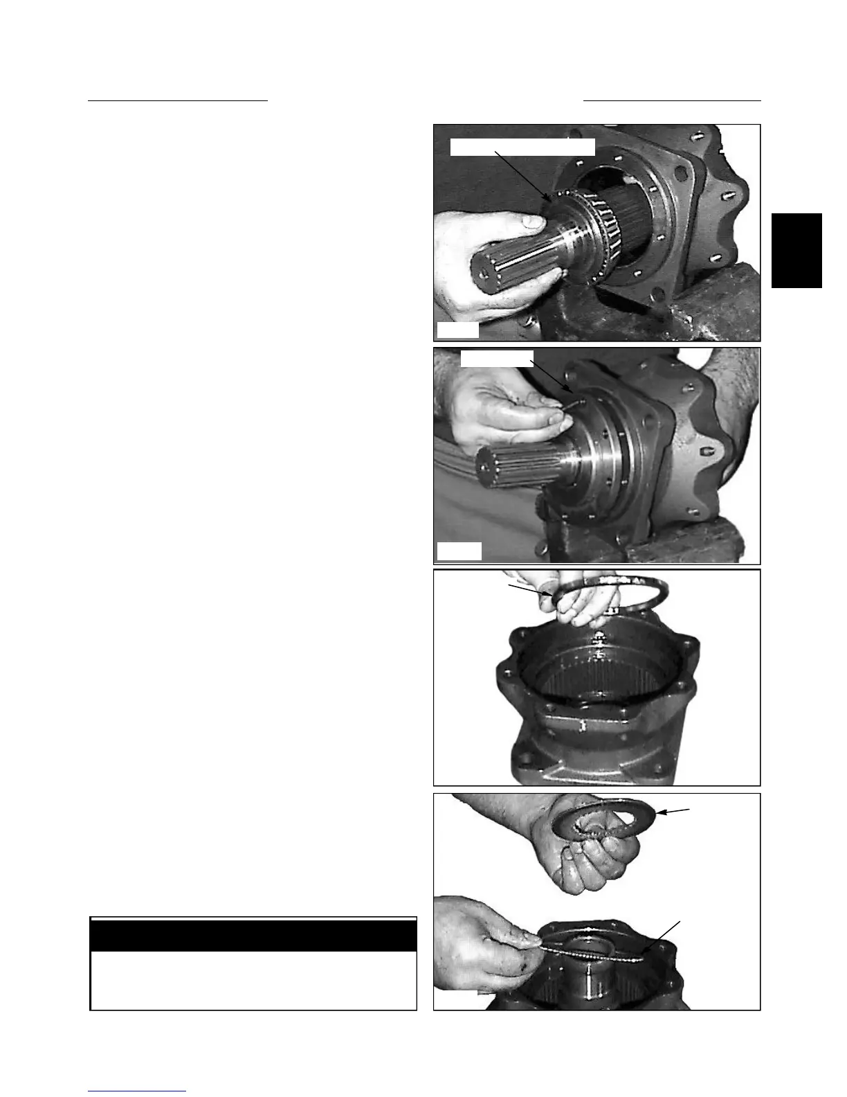
1 Install the output shaft to the housing. (fig. C2321)
Assembly
4 Install the brake disc plates. (fig. C2323, C2324,
C2319) Start with a fibre plate, add a steel plate, then
fibre and so on until the last plate to be installed is a fibre
plate.
3 Install the brake disc spacer ring to the housing. (fig.
C2320)
2 Install the front cover to the housing and torque the
screws to 8.9 ft lbs (12 Nm). (fig. C2322). Use new seals
when assembling the motor.
Front cover
Output shaft and bearing
Spacer ring
Add fibre plate first
Steel plate
NOTE: The fibre plates are also called outer plates
due to the “teeth” outside of the plate.
IMPORTANT