2-35
DRIVE MOTOR 2.12
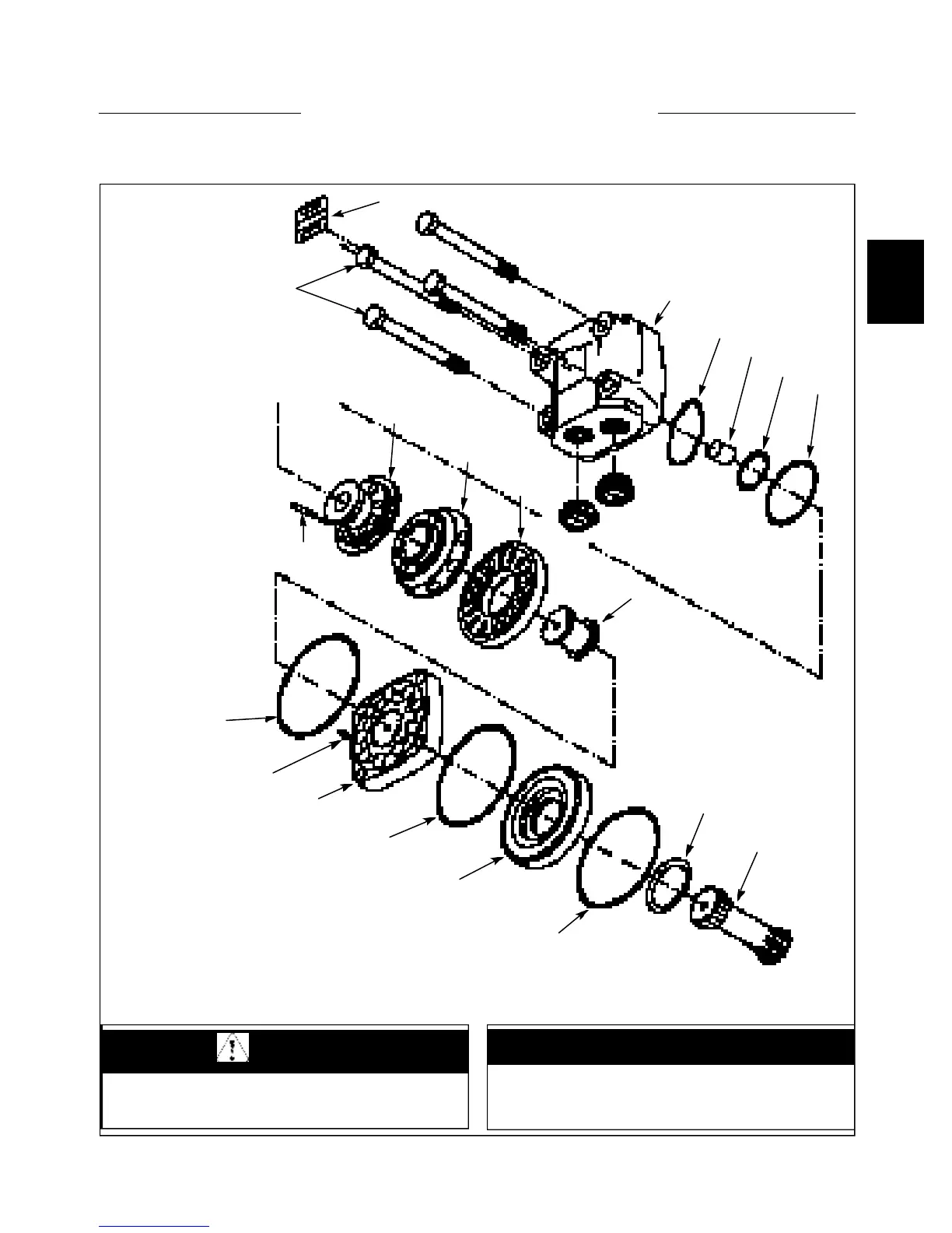
Parts Illustration
Fig. C1892 shows an exploded view of the hydraulic
torque motor. Before disassembling the torque motor,
clean the outer surface of all loose dirt and grease and dry
with compressed air. Be sure all openings are plugged to
prevent solvent or soap entering the torque motor.
1. Name plate
2. Bolts
3. Valve housing
4. Spring washer
5. Spacer
6. O-ring seal
7. O-ring seal
8. Valve drive shaft
9. Channel plate
10. Disc valve
11. Balance plate
12. Guide pin
13. O-ring seal
14. Guide pin
15. Gearwheel set
16. Intermediate plate
17. O-ring seal
18. Conical seal ring
19. Cardan shaft
C1892
Danfoss OMT FL
Diagram C1892 Index
1
2
3
4
5
6
7
8
9
10
11
12
13
14
15
13
16
17
18
19
WARNING
To avoid eye injury, use safety goggles when clean-
ing with compressed air.
When making repairs to the hydraulic system, keep
the work area and parts clean. Use caps and plugs
on all open line and ports.
IMPORTANT