1-23
6 Disconnect the return line from the control valve and
remove the adapter fitting. Plug and cap all open ports
and hose ends.
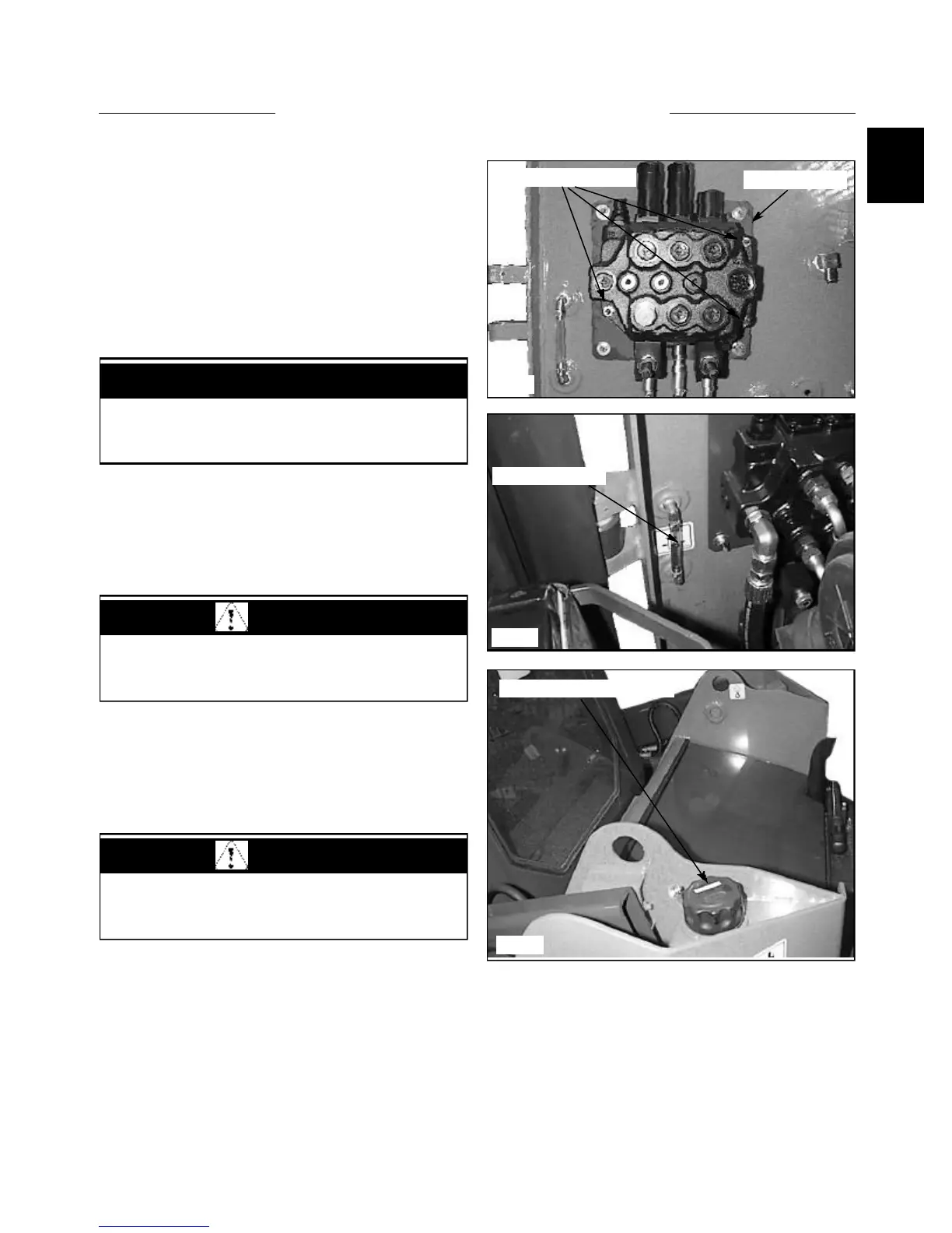
7 Remove the 3 nuts holding the control valve to the
mount and remove the control valve.
8 Remove any fittings left in the control valve. Cap all
open ports to prevent contamination. Place these fittings
in the new or repaired control valve. Be sure to check all
fitting flares and o -rings for damage and replace as
required.
9 Assemble the control valve to the loader in the
reverse order above. Torque the bolts holding the control
valve to the mount at 15 ft lbs. (20.4 Nm)
10 After all connections have been made, including the
control valve electrical connections, check the oil level in
the hydraulic reservoir and top off if necessary.
11 Start the engine and cycle the various hydraulic
functions to check for leaks. Make sure the control valve
lock system is functioning properly. Do not use your
hands to check for leak locations, fluid under operating
pressure can penetrate the skin and cause serious personal
injury.
12 After checking for leaks, you must retest the relief
valve setting as outlined on page 1-6 Testing and
adjusting.
C1878
C1879
Check fluid level
Replenish fluid as required
C1867
CONTROL VALVE 1.3
Follow the hydraulic fitting torque chart in Section
1.10 when connecting fittings and lines.
IMPORTANT
WARNING
Use extreme caution when checking the hydraulic
system for leaks. Fluid under pressure can penetrate
the skin and cause serious injury.
WARNING
All safety switches must be connected and
functioning to prevent possible operator injury.
Mounting plate
Control valve mounts