3-8
CHAIN TIGHTENER 3.4
Chain Tightener Removal
1 Remove any attachment, raise the boom arms and
engage the boom support pins. Shut off the engine.
2 Block the loader securely with all four wheels clear
of the ground.
3 Remove the wheels from the side of the loader to be
repaired.
4 Drain the lubricating oil from the final drive housing.
Refer to Section 3.2 page 3-3.
5 Remove the final drive inspection cover located
between the 2 axles.
6 Loosen the chain tightener and adjuster and discon-
nect the chain. Refer to Section 3.3 page 3-5.
7 Rotate the front axle and pull the excess chain rear-
ward through the chain tightener sprocket. Leave the
chain in the housing.
8 Remove the 3 chain tightener nuts. You may require
some help to hold the tightener assembly as you release
the nuts. The tightener is now free to be removed.
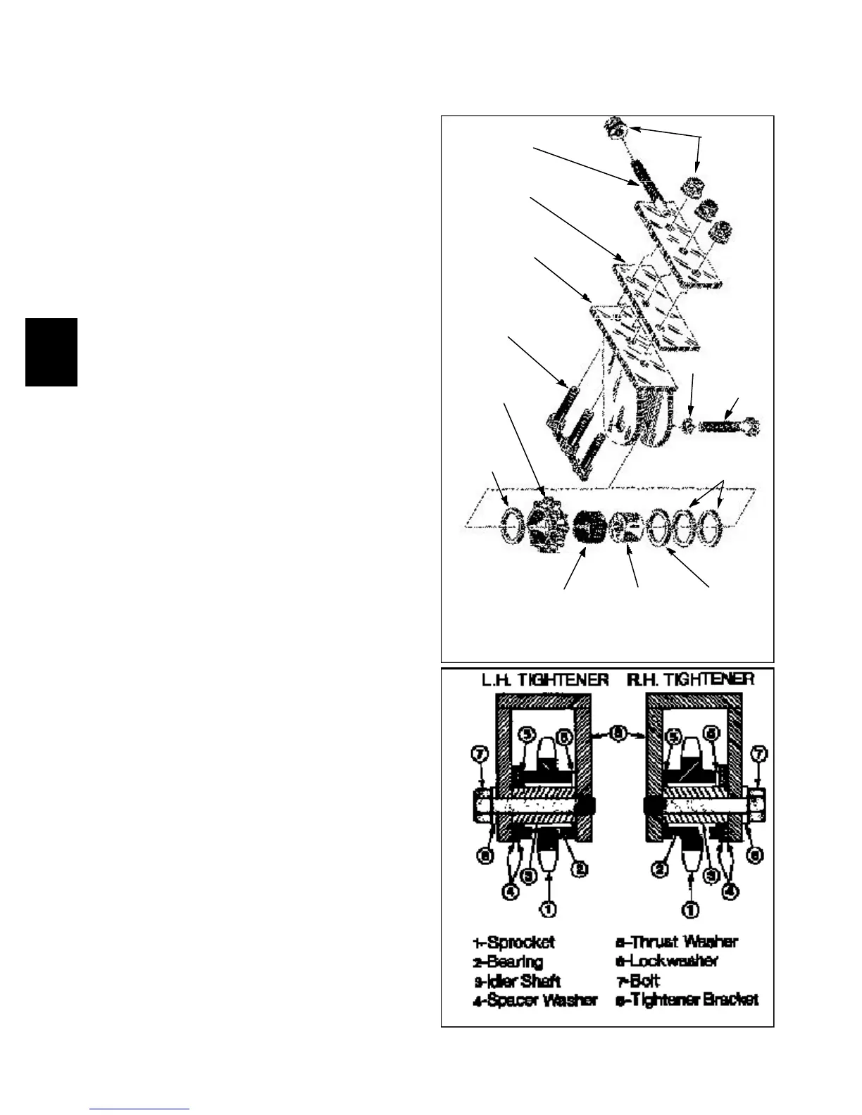
C1173
Adjuster plate
Support plate
Tightener bracket
(L.H. & R.H.)
Tightener bolt
assembly
Sprocket
Thrust
washer
Cage roller
bearing
Idler shaft
Spacer
washer
Thrust
washer
Bolt
Lock washer
Flange nut
Inspection
Follow fig. C1173 to disassemble the chain tightener
assembly. Note the finely machined thrust washers used
on either side of the sprocket. The 2 spacer washers are
used to align the sprocket with the axle sprocket and
chain. The spacer washers are always used next to the
head of the bolt, away from the threaded side of the tight-
ener bracket.
Inspect the thrust washers, sprocket, sprocket bearing sur-
face, bearing and idler shaft for scaring or excessive wear.
Replace worn parts as required.
When assembling the new components, use Loctite type
609 (red) to the threaded area of the tightener bracket
assembly. Torque the bolt to 180 lbs/ft (245 nm).
C233
R.H Tightener Assembly Shown