14
2. CONTROLS
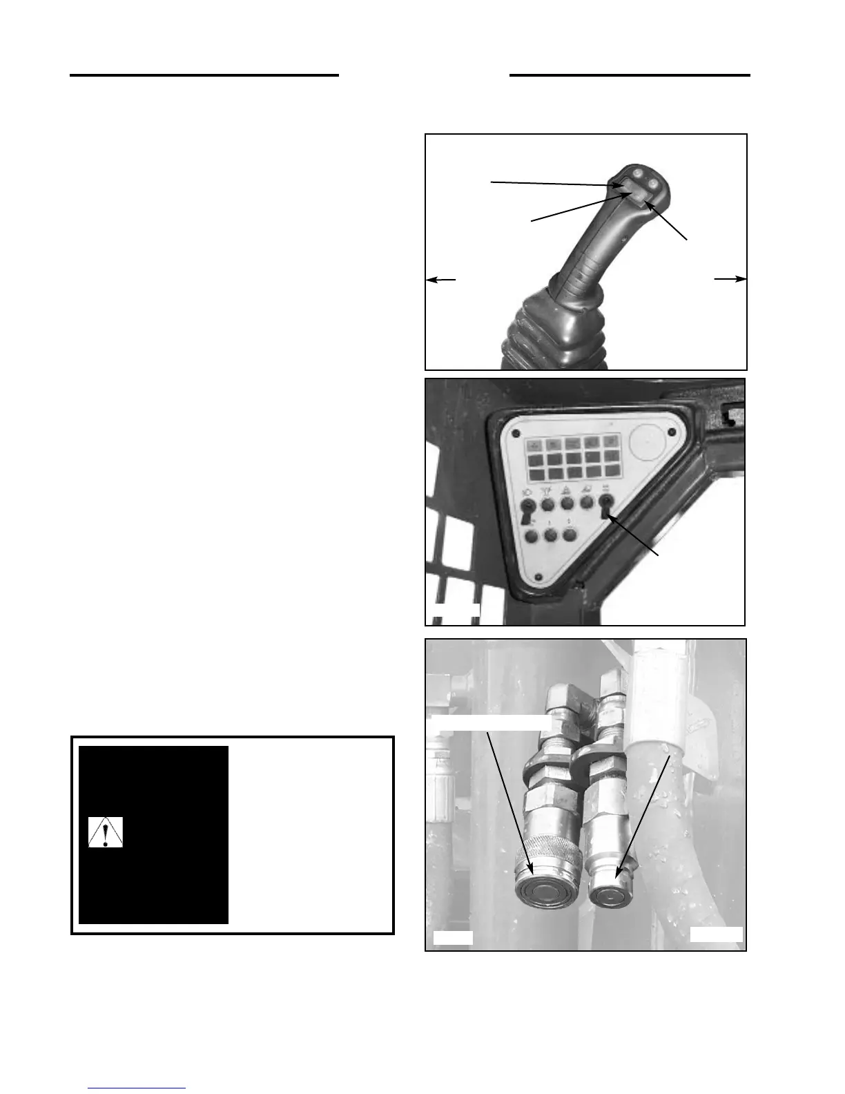
C3793a
Fig. 2.8B
C3015
Fig. 2.8A
C4086
Fig. 2.8C
2.9 ELECTRIC SOLENOID
AUXILIARY CONTROLS
Auxiliary hydraulics (solenoid operated - standard)
A switch located on the L.H. steering control lever (Fig. 2.8A)
is used to engage the loader’s auxiliary hydraulic circuit to
power attachments such as post hole augers, sweepers, etc.
Pressing and holding the switch in position 1 (fig. 2.8A)
provides hydraulic flow to the female quick connect coupling
located at the front of the lift arms (fig. 2.9C). Releasing the
switch returns the auxiliary hydraulic circuit to neutral,
stopping the hydraulic flow.
Pressing and holding the switch in position 2 (fig. 2.8A)
provides hydraulic flow to the male quick connect coupling
located at the front of the lift arms (fig. 2.8C). releasing the
switch returns the auxiliary hydraulic circuit to neutral,
stopping hydraulic flow.
For continuous flow to the auxiliary hydraulic circuit, a toggle
switch is located on the L.H. instrument panel (fig. 2.8B).
Placing the switch in the “ON” position provides continuous
hydraulic flow to the female quick connect coupling located
at the front of the lift arms (fig. 2.8C). To stop hydraulic flow
to the auxiliary hydraulic circuit, return the switch to the
“OFF” position (fig. 2.8B). When the switch on the
instrument panel is in the “ON” position, the switch located in
the L.H. control lever is not operable.
NOTE: See Section 2.2 for information on the control
handles.
AUXILIARY HYDRAULIC CONTROL
1
2
NEUTRAL
ROPS SIDE
SEAT SIDE
TOGGLE
SWITCH
T avoid persinal injury,
lower the lift arms, shut off
the engine, raise the seat bar
and cycle the controls to
ensure they are locked.
Then, unlatch the seat belt
and exit the loader. Do not
enter or exit with the engine
running unless as specified
in this manual or under
specific service and backhoe
operating procedures.
WARNING
Male Quick Coupling
Female Quick Coupling