13
To operate the lift arm supports, first remove any bucket or
attachment from the quick - tach; raise the lift arms to full
height and shut OFF the engine. Push the two lift arm
support pin handles located directly in front of the operator
at the top of the operator compartment (Fig. 2.6A) outward
extending the lift arm locking pins (Fig. 2.6B). Slowly
lower the lift arms down onto the pins. To retract the
support pins, first lift the lift arms off of the pins before
retracting.
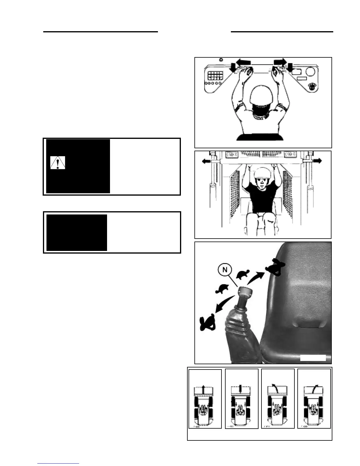
2. 8 STEERING CONTROLS
The two steering levers control speed, direction and
turning of the loader. The R.H. lever controls the wheels
on the R.H. side of the loader and the L.H. lever the L.H.
wheels. Loader speed is controlled by the amount each
lever is moved from centre or neutral position. (Fig. 2.7A)
The further away from neutral the faster the travel speed.
For maximum power and slow travel speed move the
control levers only a small amount.
To drive the loader forward in a straight line, move both
control levers forward the same amount (Fig. 2.7B).
To drive the loader in reverse in a straight line, move both
control levers back the same amount (Fig. 2.7B).
The loader is turned by moving one lever further forward
than the other. To turn right, move the left lever further
than the right lever. To turn left, move the right lever
further than the left lever (Fig. 2.7B).
For the loader to turn or “skid-steer” within its own length,
one lever is moved forward and the other back. This causes
the wheels on one side to turn forward and the wheels on
the other side to reverse turning the loader (Fig. 2.7B).
Fully retract the lift arm
supports before raising
or lowering lift arms.
IMPORTANT
2. CONTROLS
C - 694
Fig. 2. 6B
C3135
Fig. 2. 6A
C3938
Fig. 2.7A
C - 696 - 9
Fig. 2.7B
FORWARD REVERSE
LEFT TURN RIGHT TURN
To avoid personal injury do
not start the engine unless
you are in the seat with the
seat belt fastened around
you, unless as specified in
this manual or under
specific service and backhoe
operating procedures.
WARNING