Notes: - Alignment below should be done after 15 minutes warm up of TV.
3.4. G2 & FOCUS
3.5. SUB COLOR
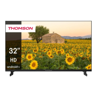
a) Input NTSC Video pattern : AV
b) Press key "4" : page 4. (Fig.4).
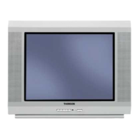
Measure at the CRT blue Cathode (Fig.5).
c) Adjust COLC to make level a and d equal;
then TNTC to make level b and c equal;
d) Input PAL color bar signal.
e) Adjust COLP to make level of a,b,c,d equal ;
f) Input SECAM color bar signal, and adjust
COLS to make level of a,b,c,d equal.
3.6. WHITE BALANCE
White Balance adjustment (neutral)
a) Input RF Black and White pattern signal (PAL).
b) Press "1" key to enter white balance adjustment (Page 1:Fig.6)
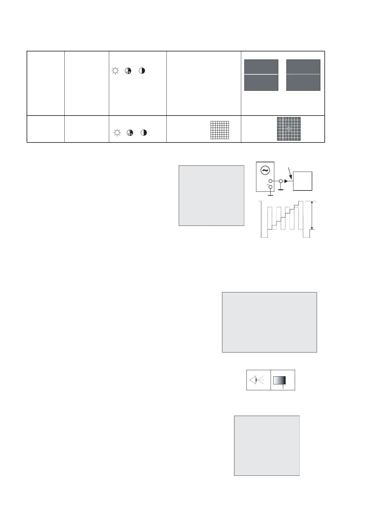
c) Measure the dark side of the picture with a color analyzer.
Adjust RED and GRN until the data on the analyzer
become x=284 +/-8, y=299 +/-8.
d) Measure the bright side of the picture.
Adjust WPR, WPG and WPB until the data on the analyzer
become x=284 +/-8, y=299 +/-8.
e) Repeat step c and d until you get right white balance
on both dark and bright side of the screen.
f) Input RGB Black and White pattern signal (PAL).
g) Measure the dark side of the picture with a color analyzer.
Adjust REDC and GRNC until the data on the
analyzer become x=284 +/-8, y=299 +/-8.
h) Measure the bright side of the picture.
Adjust WPRC and WPGC and WPBC until the data on the
analyzer become x=284 +/-8, y=299 +/-8.
i) Input SECAM L Black and White pattern signal.
j) Measure the dark side of picture with a color analyzer,
Adjust REDSECAM and GRNSECAM until the data on
the analyzer become x=284 +/-8, y=299 +/-8.
Warm color temperature
a) Press green " LIST" key .
b) item: Warm R ; Warm G ; Warm B : Factory adjust
c) Check the item values are as shown opposite.
Alignment of Cool color temperature
a) Press green " LIST" key.
b) item: Cool R ; Cool G ; Cool B : : Factory adjust
c) Check the item values are as shown opposite.
(minimum visible intensity).
 Loading...