60
Resetting the Zero
Point
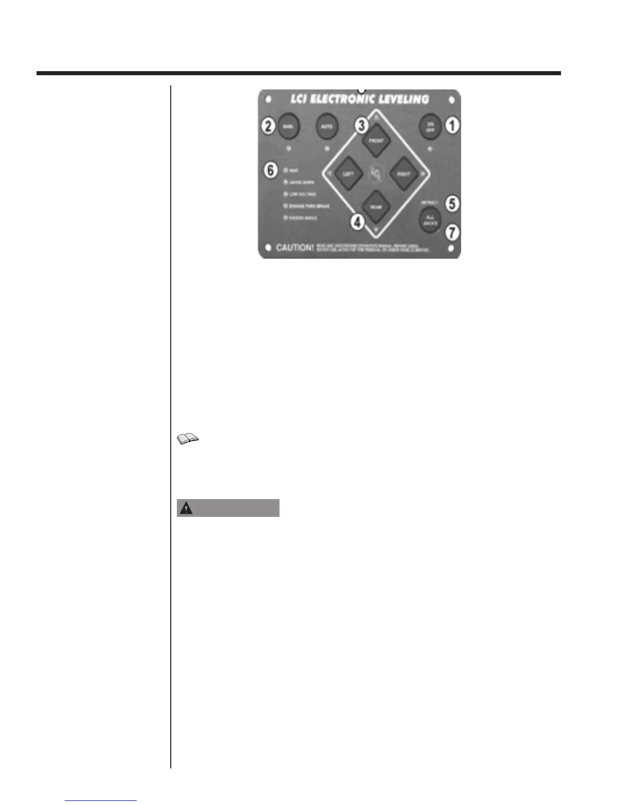
1. Turn the system on by pressing the “ON/OFF” button (1). The “ON/OFF” button
will illuminate.
2.Press the “MAN” button (2) and hold for 2-3 seconds. The indicator light will
illuminate.
3. Manually level the coach using a carpenter’e level ON THE FLOOR of the coach.
Level front to rear and then left to right.
4.Turn the panel off; then turn it on again.
5.With the coach leveled press “FRONT” (3) ve times.
6. Press “REAR” (4) ve times. All the lights on the panel will ash.
7. The panel is now in idle mode. If the coach has come out of its level condition , it
can be reset by pressing the directional buttons to get the coach level again. If the
coach is in level condition, Press the “RETRACT ALL” button (5) three times.
Emergency
Retraction Procedure
FOLLOWING MANUAL OVERRIDE OPERATION,
FAILURE TO RETURN ALL VALVES TO NORMAL
POSITION MAY RESULT IN ONE OR MORE JACK LEGS
DRIFTING DOWN FROM THEIR RETRACTED (STOWED)
POSITION. FOR CARTRIDGE VALVES, ROTATE THE
CENTER SCREW FULLY COUNTER-CLOCKWISE.
Note: Zero point is set at the time the unit leaves the production facility.
Resetting of the zero point is concidered owner maintenance and as such not
covered under the TMC warranty.
In the event of electrical failure, the jack leg(s) may be retracted manually by following
the procedure below.
1. The individual cartridge valves are clustered together on the side of the pump
manifold.
Locate the screws on the appropriate cartridge valve(s).
Using a 5/32" Allen wrench, turn the screw(s) clockwise until all the way in.
Note: The normal operating position of the screw in the cartridge valve is
the counter-clockwise ‘out’ position. The only time the valve should
be shifted manually is when attempting to operate jack(s) via
manual override.
2. Remove the plastic cap from the top of the motor and disconnect the power cables.
3. Attach a 1/2" socket to the motor's coupler and drive it with a drill, ratchet or similar
Controls and Operations