Chapter 5: Common Operating Circuits
13056-S01 Page 10
Chapter 5 Common Operating Circuits
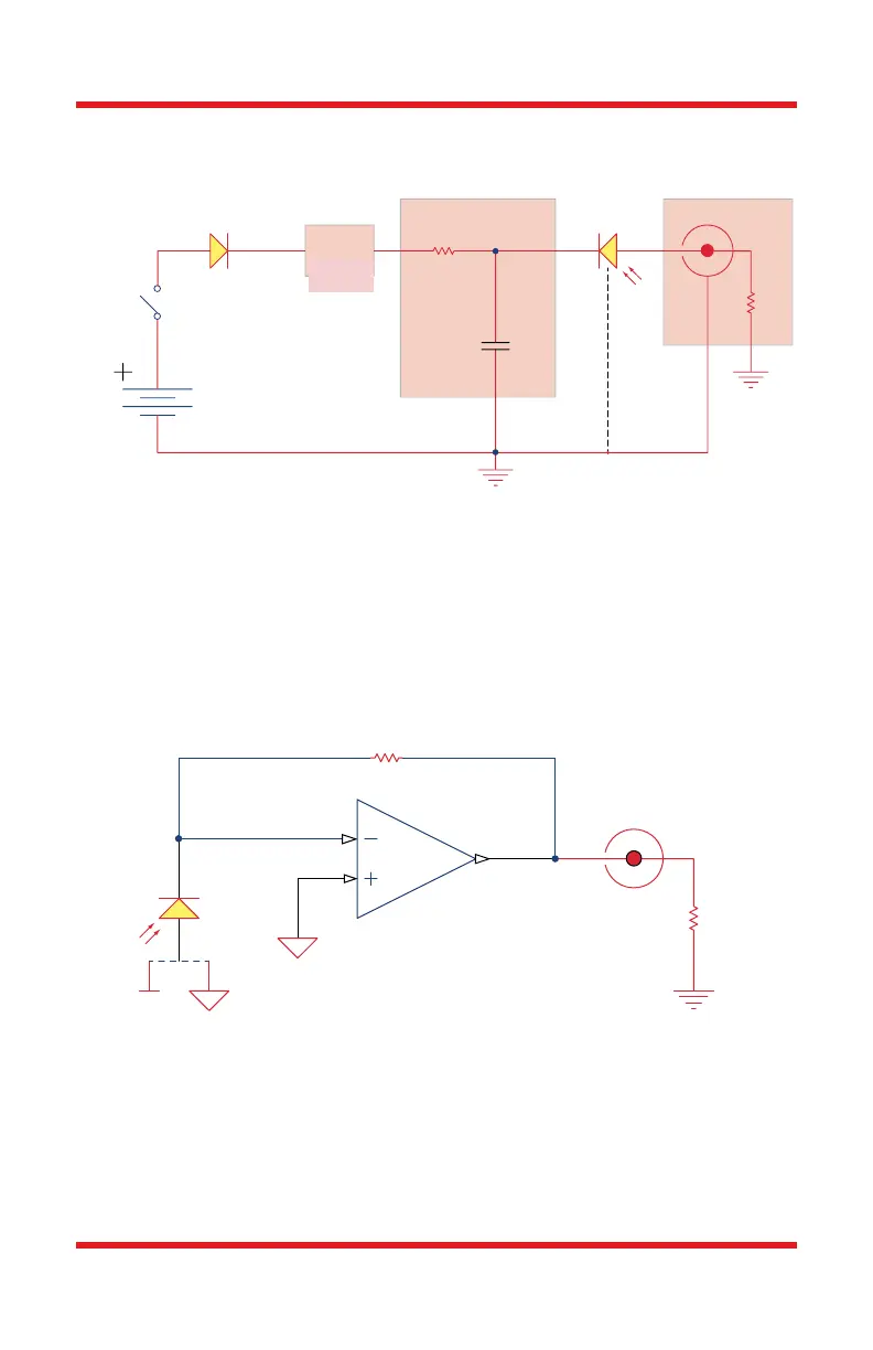
Figure 2 Basic DET Circuit
The DET Series Detectors are designed according the circuit depicted above.
The detector is reverse biased to produce a linear response with applied input
light. The photocurrent generated is based upon the incident light and
wavelength and can be viewed on the oscilloscope by attaching a load resistance
on the output. The function of the RC Filter is to filter any high frequency noise
from the input supply which may contribute to a noisy output.
Figure 3 Amplified Detector
On/Off
Switch
Protection Diode Photodetector
V
BAT
RC Filter External
Resistor
1 kΩ
Capacitor 0.1 µF
V Bias
BNC
GND
GND
Battery
Voltage
Regulator
5V
R
LOAD
Photodetector
Transimpedance Amp
Out
Feedback
R
F
A
B
-V
BNC
GND
GND GND
R
LOAD
10 V