Calibration & Measurement Module for OTKB/OTKBFM Chapter 5: Operation
Page 11 Rev C, August 2, 2018
4. Start the Stage Oscillation in the OTKBFM-CAL software, use an amplitude appropriate for the bead size,
e.g. 3 µm for a 1 µm bead, and set the frequency to 1 Hz.
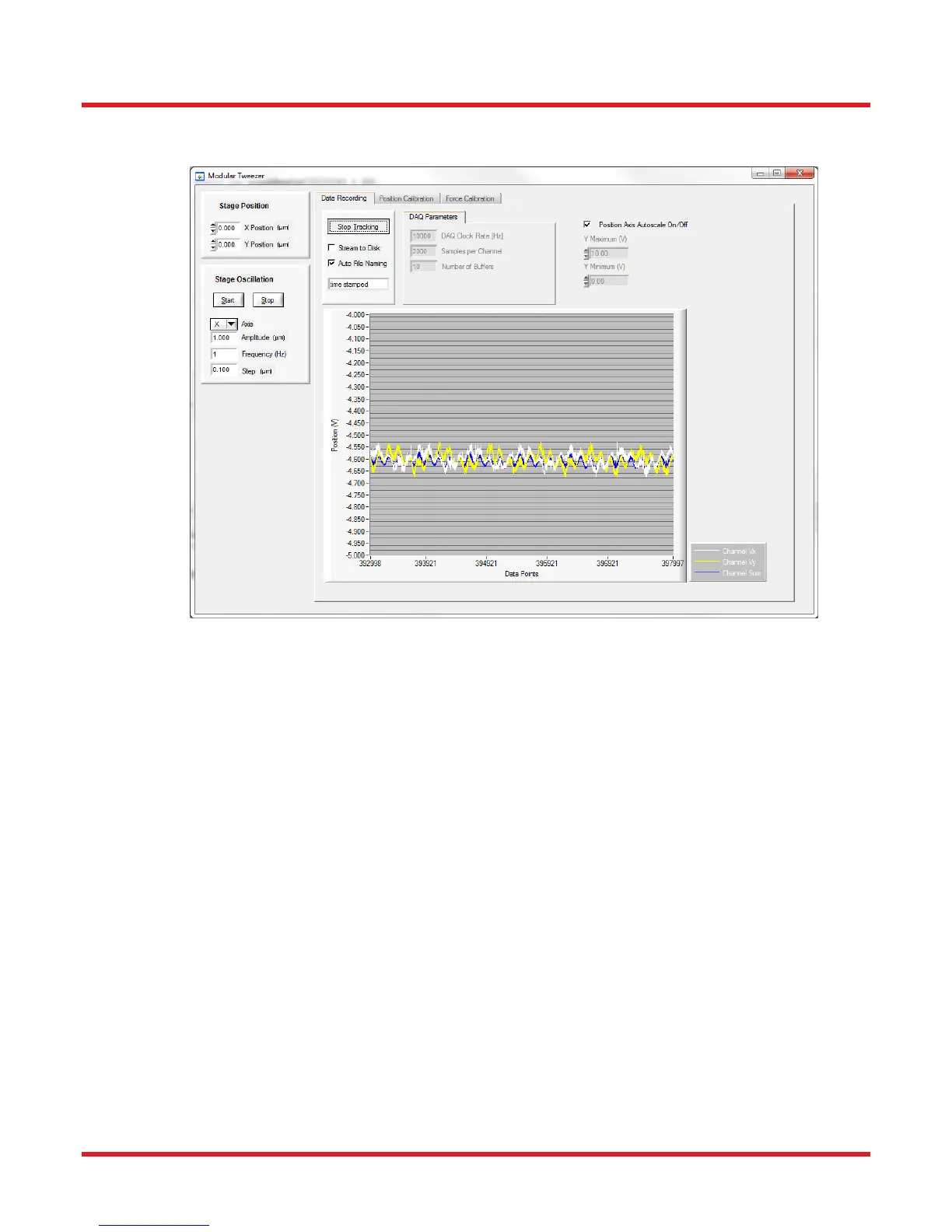
Figure 8 Example Trace of Detector Voltage Signals
5. Use the “Stage Position” adjusters to change the bead position relative to the trap position until you see a
significant change in the voltage signals during the state oscillation. (Hint: The stuck bead is aligned with
the optical trap center when the voltage signal changes most significantly for Vx and Vy.)
6. Stop the stage oscillation and select the “Position Calibration” tab in the software. Click “Calibration”.
7. If the X and Y plot versus position show the crossing of the bead through the trap, click on the left and
right side of the graph to move the limits for the automatic linear fit. The beta value is shown on the right
hand side in the box labeled “Slope”.
 Loading...