Calibration & Measurement Module for OTKB/OTKBFM Chapter 3: Introduction
Page 3 Rev C, August 2, 2018
Chapter 3 Introduction
The capability of optical tweezers to exert measurable forces on micron-scale, dielectric particles offers a unique
and valuable tool for studying cell components, such as biological polymers and molecular motors. In many
investigations, optical tweezers need to apply precise force to functionalized microspheres that have been
attached to molecules of interest. For small displacements from the center of the trap, optical tweezers apply a
force toward the focus of the trapping laser beam with a magnitude proportional to the distance of the particle
from the focus. This allows the optical tweezers to be modeled by Hooke’s law, F
i
= -k
i
x
i
, where k
I
is the spring
constant and x
i
is the displacement from the center of the trap.
In order to allow quantitative measurements the optical tweezers system needs to be calibrated. While there are a
couple of different approaches, the most common technique is based on back focal plane detection.
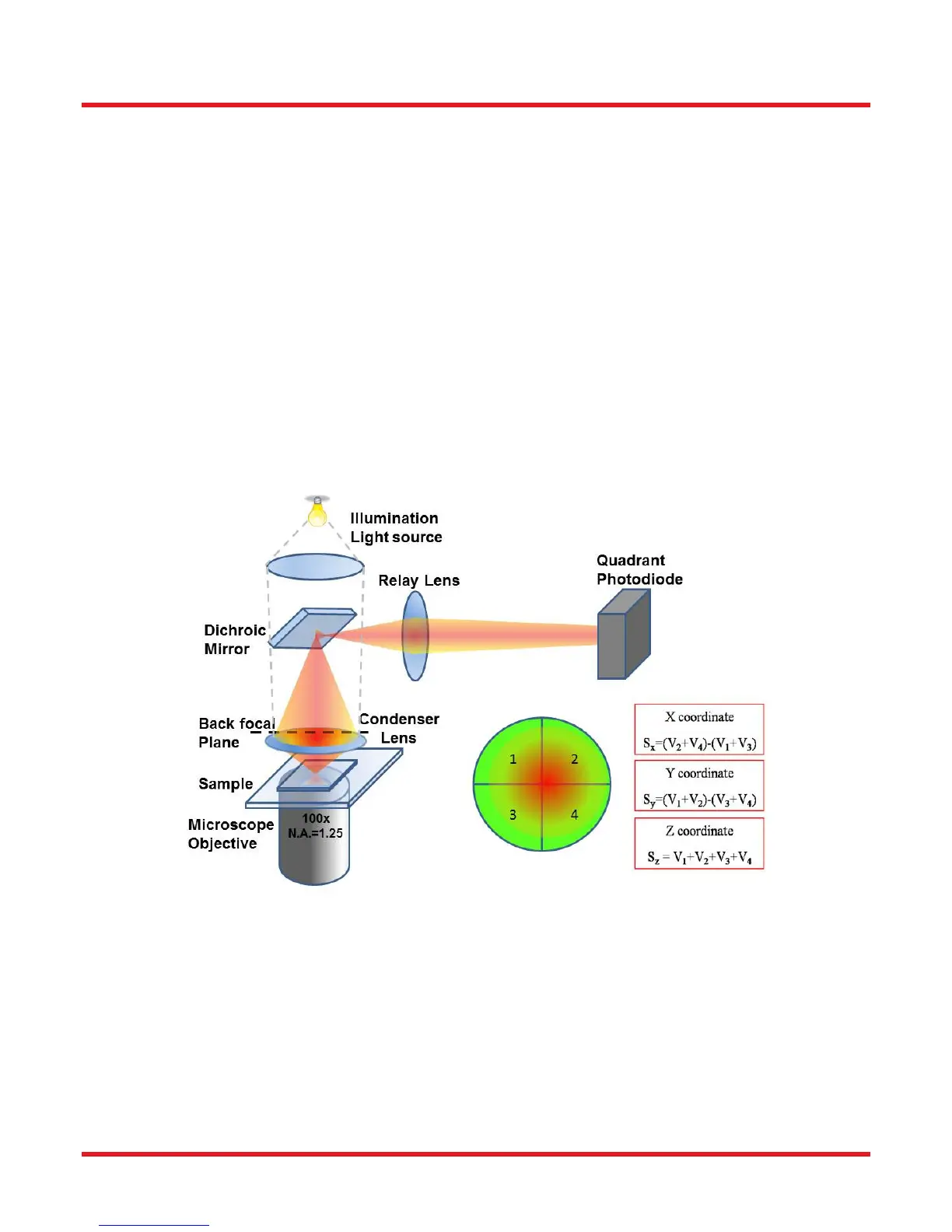
As the laser beam passes through the sample plane interference occurs between the light which is transmitted
through the trapped particle and the remainder of the light. As a consequence the interference pattern at the back
focal plane of the condenser depends on the distance of the trapped particle to the trap center. The deflection is
converted to an electrical signal by a quadrant photodiode, which produces a voltage proportional to particle
position for small displacements from the center of the trap. Accurate force measurements depend on precise
calibration of the spring constant (also called stiffness), k
i
, and the sensitivity of the particle position detector,
which vary with laser power and particle properties.
Figure 1 Schematic of the optical train of a tweezers setup with back focal plane detection. The
inset illustrates how the X, Y, and SUM (S
x
,S
y
,S
z
) signals are calculated.
In the following sections, two methods to determine the trap stiffness are described. Since each method relies on
a different physical principle, the combined results provide a convenient way to verify the calibration.