Calibration & Measurement Module for OTKB/OTKBFM Chapter 6: Frequently Asked Questions
TTN030035-D02 Page 14
Chapter 6 Frequently Asked Questions
1. The OTKBFM-CAL software will not start. What should I do?
a. Check that the system is connected to the power source and the computer through the provided
power supply and the USB cables respectively.
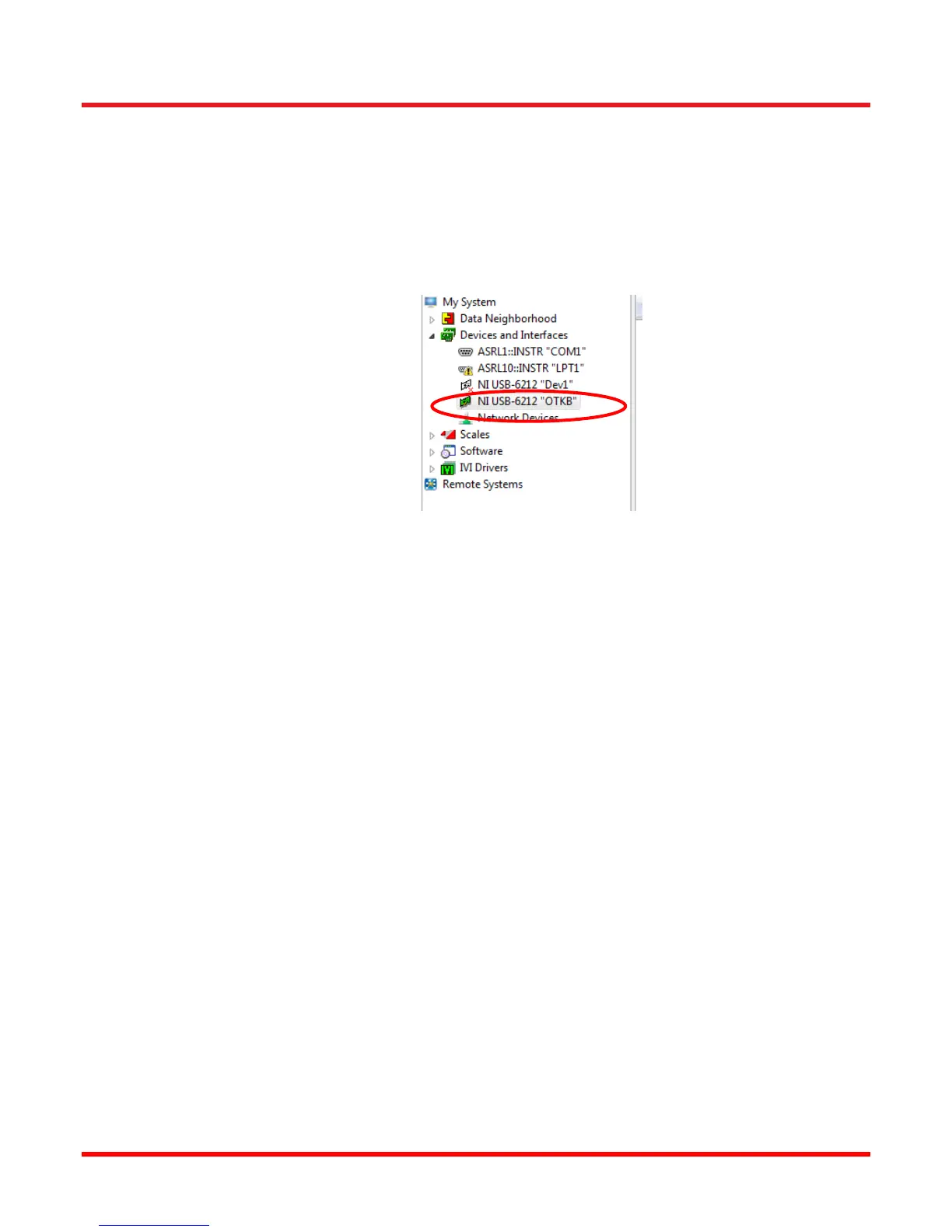
b. Check that you have changed the default name of the DAQ card through NI MAX software. The
default name the USB-6212 card used is “OTKB”.
2. How come I cannot control the NanoMax stage with OTKBFM-CAL software?
a. Make sure that all cable connections are correct. Check the connection between calibration
module and the K-Cube controllers. Make sure the piezo and strain gauge cables connect to the
corresponding axis on the stage. Check the USB connection between the calibration module and
the PC.
b. Using the APT software, make sure that the K-cubes are functional, i.e. they show up
automatically after starting APT User. If the APT User software cannot identify any of the K-cubes
in the hub, power cycle the K-cube hub. Then identify the K-cube piezo and strain gauge
controller pairs connected to the X and Y axis on the stage. Set the piezo cubes to ‘Open Loop’
temporarily and adjust the piezo voltage to zero.
Next use the NI MAX softare and select ‘Test Panels’. Set a DC value of 0V for analog output
ao0 and ao1.
At this point you can verify that the cabeling between controller and stage is correct: temporarily
adjust the piezo voltage to some positive value and observe if the strain gauge controller shows
the position change. If the strain gauge does not show a position change check the cables to the
stage. Finally set the piezo voltage back to 0V.
Now select the ‘Zero’ button on the strain gauge controllers and wait until the controller has found
its zero setting. Afterwards switch the piezo controllers for X and Y back to closed loop.
Close the NI MAX software and start using the OTKBFM-CAL software.
3. There is an offset when I start oscilating the NanoMax stage. What is the reason?
a. This can be caused by zeroing the strain gauge while a voltage signale other than 0V is applied
to the corresponding external input of the piezo controller. Please follow the setup described
under point 2 to remove any such offset.
 Loading...